DJI FPV

I got a new DJI FPV for Christmas. Here is the first flight.

The video quality is great but hard to share here. I converted the video quality from 4K: 3840×2160 at 50/60fps with 3:17 runtime @ 3.5GB down to 720p 30 fps shrinking it to 72.2MB.

Overall the flight was great for the first time. The controls were super easy. The heads up display gave great information without overdoing it. Return to home worked perfect. I let the battery drain down and it automatically returned to home with 10% battery remaining.

I did have the propeller guards on and it recognize them and reduced the performance. During full decent it did shake around some and I think that it is related to the guards. It also likely reduced the flight time. Next time I think I will go without.

Flight time was somewhat shorted than I thought it would be. I am glad I got the Fly More option that came with 2 extra batteries and a charging hub. The hub does only charge one battery at a time and can take an hour for each battery.

I was impressed by a few notifications. It noticed the propeller guards automatically and adjust the performance accordingly. I did go to 250M and it gave a warning about cross winds. There was zero wind a ground level.

I had a good time and look forward to going out again. I even registered for Remote Pilot Certificate from the FAA which was quite easy since I have my private pilots license.

Simple Fix Workflow

I though that I would share my standard work flow for fixing a simple household item.

Step 1: I tend to start by doing a rough sketch of the item I am drawing. This serves two purposes. First is give me the rough idea of what I am going to create. Most of the time when I am fixing an item it is as simple as tracing an item that I already have. The second purpose is to describe the dimensions of the object.

Step 2: CAD design. Using the drawings and dimensions I translate this to a 3-D model. This is actually a 2 step process for me as I usually take the 2-D drawing and create a sketch. I then extrude the sketch into the 3rd dimension to make the 3-D model.

I tried something new and captured a screen cast of my design process with Autodesk fusion 360 using Screen Cast Recorder. I did a one shot capture and did not edit it at all. As such there are a few extra clicks but over all I did pretty good. This was such a simple design that I did not think that I needed commentary. Maybe for the next one I will add some voice overs or text to describe my steps.

Step 3: Convert to STL and 3-D print. This is a simple process and I use Simplify3D to generate the SVG for my printer.

As you can see in the image above that it came out great the first time. I printed 2 at the same time an total print time was 45mins.

All together from removing the broken part to putting a new part in place was just over 1 hour.

Shaper Origin

Aside

Check out the Shaper Origin.

https://shapertools.com

I agree with the recent hackaday post that it’s is a game changer tool.

Hands-On the Shaper Origin: A Tool That Changes How We Build

Perorders have started and if you choose to preorders one too here is a $100 off coupon.  Best part is that I get $100 off also. So please use this link when preordering.  They are justifiably selling like gang busters so if I were you I would get in on the ground floor like I did.

https://preorder.shapertools.com/ref/VPELNQP6U

I hope to make another post soon on ths subject to better explain why I choose this tool and my thoughts on the advantages and challenges they are going to face.

Cow Tech Ciclops 3D Scanner – Part 2

Kickstart Parts

Here is what you get for the $99 from the kickstart

20160724_112516

The scanner is Arduino UNO based.  In this case they went with a clone (which I think is fine). They rolled a shield for the UNO and it looks quite professional.

20160724_150448

The stepper driver which is a daughter board to the shield looks like it is off the shelf but does not have any branding (probable just too small).  It does have a small heat sink which is probably advised.

20160724_153306

The camera is a Logitech C270 webcam that is capable of 720p.  The two laser line generators are class IIIa 5mw.  Most of the parts are .25 acrylic and they look like they are cut well.  The table stepper is a 17HS2408 which is NEMA 17.

It is interesting that they went with a large steel bearing for the rotating table used on its side.

Printed parts

The parts in general are well designed.  Some parts do need significant supports to be generated.  I would have like to see the supports minimized but over all I think they are at an acceptable level.  The print volume is a total of about 333 cm³ and took approximately 15 hours of printing.

20160724_112150

That’s it for now.  On to the next step soon.

Cow Tech Ciclops 3D Scanner – Part 1

Before I jump into the topic I have this disclaimer, I will be doing this subject over several smaller post that hopefully will be more regular and be less effort for me over time.

Ciclops 3D Scanner KickStarter

So last year I back a $99 3D scanner and yesterday it was delivered.

Current state of 3d Scanners

3D Scanners have been around for a while now but they really haven not taken off like 3D printers have.  There are several good reason for the limited availability and uptake of scanners.  Please note that I am not going to go into the detail of how scanners work, you can get that information form numerous sources on the inter-webs.

Cost for Performance

The first problem has been cost. Makebot released their Digitizer Desktop 3D Scanner (https://store.makerbot.com/scanners/digitizer/) at a list price of $949.  The results were quite clear.  While the scanner was an attempt at breaking into the mainstream for consumer 3D scanning it failed in most respects.  For the initial price the quality of the results were mediocre.  When you compare the price for performance they scored extremely low especially when you compare them to the Makerbot 2 which in my opinion scored really high and still does today (I am no Makerbot fan boy even though that is my only printer). Markerbot has reduced the price to $799 but that still misses the mark by a wide margin.

Enter the Ciclop 3D Scanner.  Now since it is a brand new there is not much by way of opinions yet and I have not assembled or used it.  I can only offer the reason that I backed this kickstarter.  The first is that scanning is somewhat useful concept.  It is not exactly a perfect fit for the type of work that I do which is mostly electronics hobbyist type work.  This type of work involves tight tolerance to make an closures for electronics that require technical drawings.    The price and performance promised by their kickstart campaign gives them a reasonable chance to standout where makebot failed.  Starting out at $99 is an excellent start.  I will take this opportunity to say that the true price is not $99.  The scanner does require a significant portion of the parts to be printed which is of coarse not free.  The parts come to a total of about 333 cm³ which at my standard rate would come to $83.25 (not including a significant amount of support material that are needed).

Performance

There are many limitation to 3D scanning right now and it is mostly centered around the software.  When you pay even $800 you expect to receive flawless results which may be an impossible standard give the current software problem.  On the other hand when you pay $99 for a product there is much more leniency for imperfect results (not that I expect flaw results from the Ciclop).  There are some examples out the on the failures of the makerbot scanner and others as well and almost all of them come to the same conclusion that the results are mixes at best.

Limited use

Some objects are just very well suited for scanning which makes a scanner useful.  There is a portion of the work I personal do which is replacing parts for household items for example, where a scanner may come in handy.  The question still remains about what percentage of objects fit the bill and if it makes the purchase worth it.

This post has gotten longer than promised but in the next post I will jump into the assembly of the scanner.

Electronics Repair #1 – Husqvarna Viking Designer SE Sewing Machine

The Problem

My mother was using the Husqvarna Viking Designer SE Sewing Machine but it started to exhibit some strange failure modes.

viking_DesignerSE

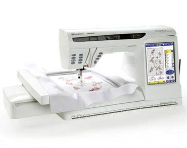
Most of the time when powered on the machine would simply lite the back light of the LCD and basically do nothing.  Occasionally (as reported by mom) the machine would turn on like normal after turning off and on the machine several times.  I was not able to reproduce this (prior to taking it apart).

My mother took it to the repair place and they wanted to replace the main board the power supply and the LCD for a whopping $2000.  Instead of settling for this she just got a newer bigger and better machine for 5 times the cost of the repair.

Step 1: Power

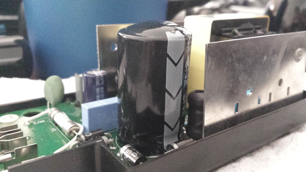
I decided to start with the obvious first, power.  This machine has what looks like a specific made power supply.  I cracked it open an haha the telltale bulge on the main filter cap.

main cap bulge

Some ordering and a bit of soldering later and …..

no dice 🙁 same problem.

Not entirely sure if the cap is dead or almost dead.   It is suppose to be 220uf and it measures 207uf which is inside the +-20% that it should be.  Its got the bulge so it cant be far from failure.

Step 2: Classifying the Intermittent Failure

This step was tough.  As all intermittent failures go they are hard to nail down.  I tried to no avail to get the darn thing to actually power on in the way my mom reported it would (reason why down below). On, off, on, off through many cycles.  It was always the same thing back-light lit but nothing else.  I tried removing various connection to its plethora of sensors and motor controls but nothing worked.  This step admittedly took the longest and I ended up shelving the project for 4 months due to frustration and lack of progress.

Step 3: Heat

So I got a bit more money back from taxes that I was expecting and I splurged on something that I was wanting to get for a while the FLIR E4.

e4_image_1

I got this lovely thing to help with this specific problem and to help fix my drafty house (and also toy around with cause it cool).

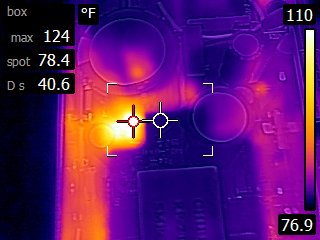
I started by poking around looking at the power supply thinking that there may still be an issue.

FLIR0007

The was a hot spot but it tuns out the component making the most heat was an inductor which is sort of as you would expect.

FLIR0013

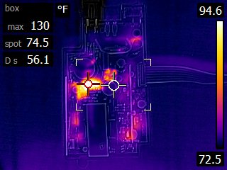
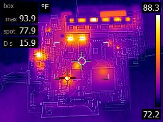
Next on to the main board.

FLIR0005

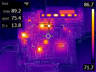
The red cross hairs and the spot to the left are motor controllers.  The series of 6 spots above are also motor controllers but they are obscured by  a copper heat spreader.  I noticed one of  the motor controllers was warmer than the rest so I examined it further.

FLIR0011 
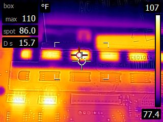
After closer inspection and more time to warm up it appears that it is no hotter that the other (un-shielded controllers).  I next moved on to two other noticeable hot spots.  the first one is a 24v to 5v dc to dc step down.

FLIR0012

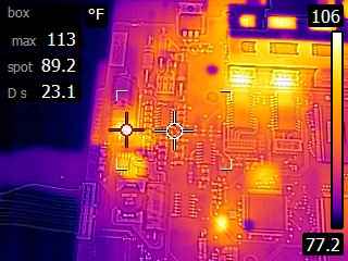
I measured out the voltages and everything seemed to be in order.  The next was also a regulator its a 3.3 to 2.5(adjustable).

FLIR0006

Close up of the area:20160310_144601

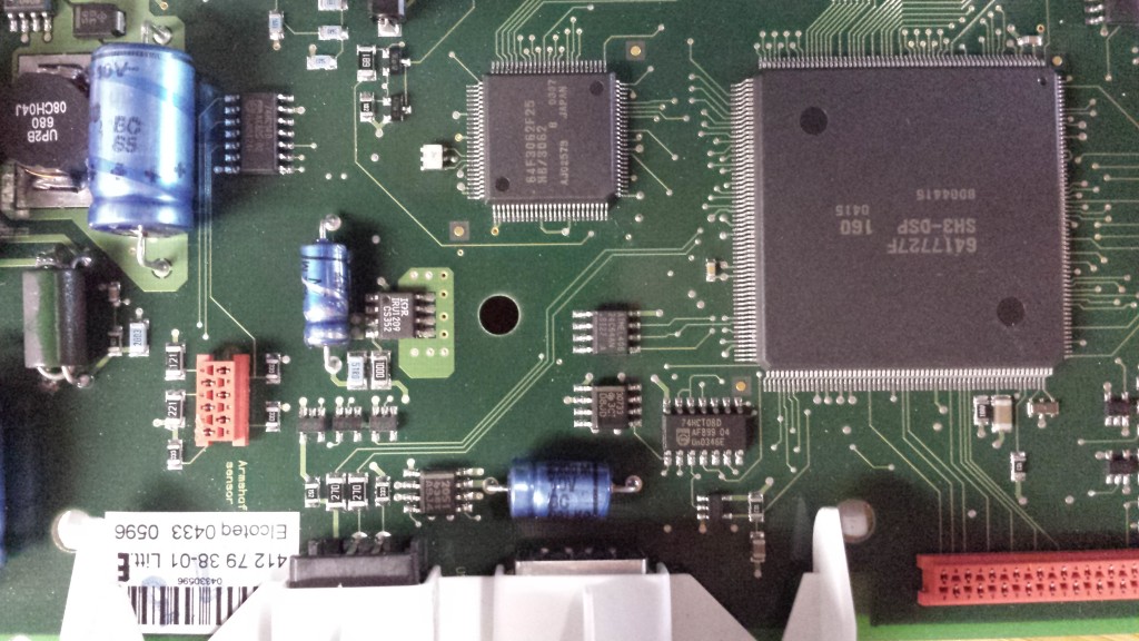
I checked the voltages here too and everything was spot on.  A bit frustrated at the prospects of hitting another dead end I thought about the intermittent problem again.  If the problem was heat related that could explain why flipping the switch a few times made it work.  Maybe it was “warming up” to make it work.  This is odd to me and I have never heard of this.  I am familiar with “cold solder joints” but they tend to manifest in the opposite, works cold and fails when warm.

To test the warm-up hypothesis I pulled out my smd rework heat gun and set it to its lowest temperature 100c.  I went for broke and started warming up everything on the board to see what would happen.  After only a few minutes of this, success!  The damn thing powered on.  This theory also makes sense why I never got it to work when trying to get it to ever work.  The bulk of my tests were with the cover off which reduced the heat load on the board.

The warm-up theory holds water yeah me!

It only took a few more minutes to narrow down the warm up spot to the second hot spot detailed above.  I was able to reliably reproduce the resolution.  From a cold board I would hold a 100c heat to that area for  6-10 seconds and the machine would power on every time.

Ok so now what?  I started by taking a closer look at the IRU1209CS regulator thinking it may be faulty.  I had already measured the voltages and they seemed fine.  I started thinking that I may need to order a replacement but after some digging it appears that it is no longer available.  At this point I was thinking great this thing may never work again.

Frustrated with replacing the regulator I moved on with a great epiphany; If this spot is so warm that electrolytic cap is mighty close to it.  I did some scrounging and I found a sort of compatible fit in my collection.  I found an radial 10uf 62v electrolytic capacitor.  I had to bodge it in a bit since I need a axial cap but I was able to just barely stretch it in there.  Low and behold the thing powers on the first time every time.

Problem solved.

Step 4: More Details

So I have never heard of a cap failing when cold (maybe I am just a novice).  So I decided to get more information.  First I measured the cap.20160310_203929

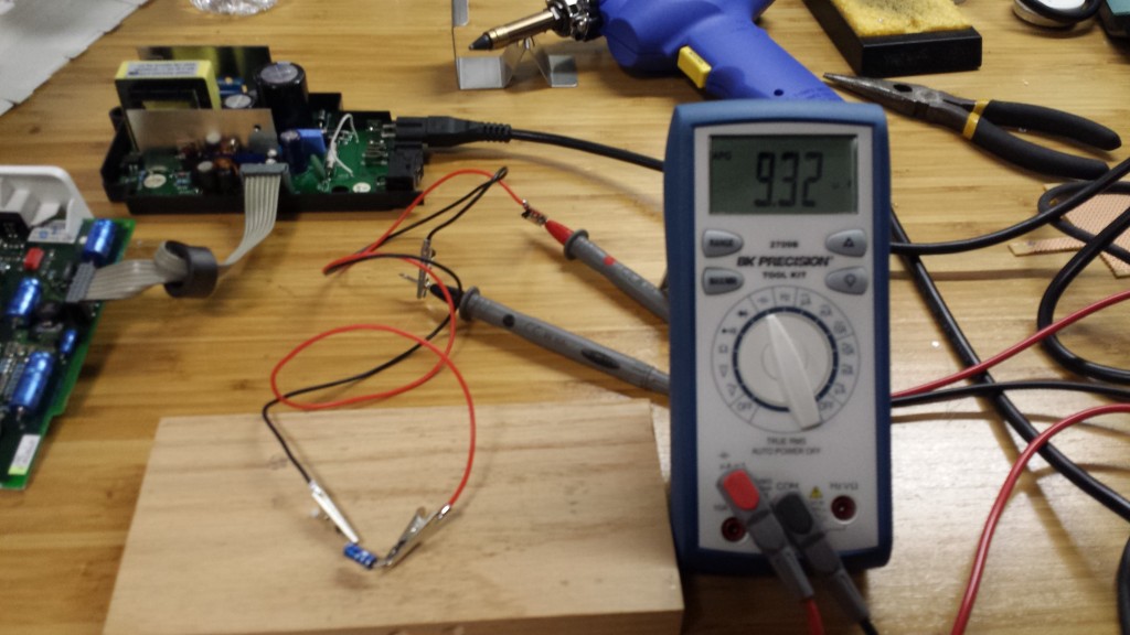
Err 9.32uf (at room temperature)…. that does not seem too bad since it is well within the +-20% (8uf to 12uf).  So what then does warming up a capacitor do?  Lets see.

As you can see heating it rapidly increases the capacitance from 9.32uf to 10.28uf and then quickly drops back down.  This is odd to me.  Is it some how getting the electrolyte working better?  I had no idea of this behavior of capacitors.  I looked as the datasheet for this cap and found this graph.

Capacitance as function of tempature

As you can see that yep, going from 20c to 90c (aprox) will increase the capacitance by a factor of 1.1 which is almost exactly what I saw in the video.  Ultimately this all means that the cap even though it was technically in spec was still not up to the task.  Or could it perhaps be that something else is going on somewhere else that needs this cap to be closer to 10uf.  Only time will tell as I have not reassembled the thing to see if its fully functional.

Conclusion

There you have it I seem to have fixed the problem, sort of saved money (potential resale value) and most important learned something along the way.  And bonus, if you are reading this maybe you learned something also or maybe just had and enjoyable time.

3D Printing – Pro Tip (2 for 1 special)

Simple and sweet rubber feet

I picked up so rubber anti vibration feet from Amazon and they work surprisingly well.  I am quite surprised a how much of the noise was coming from the feet and how much these feet reduced it.61u8-QvDD2L._SL1200_

The feet of the Makerbot do have some rubber on them but its obviously not enough.  These one don’t quite fit exactly on the right angle feet of the Makerbot but they do end up settling in relatively well.
20151031_100845

Filament spool holder

I have been using a spool holder for quite a while and it definitely worth the make SpoolHolder 3DP it uses 4 x bearing 608 which I happen to have on hand and are quite inexpensive.  The stock holder that hangs on the back of the machine does work OK but this one has several advantages.  First, for whatever reason some spools of filament are wound in the opposite direction and that requires the spool holder to be move from the left to the right on the back of the machine which is a bit annoying.  Second, this holder moves the spool from behind the Makerbot to makes it visible and easier to monitor the amount of remaining filament available.  Lastly, and maybe the most important, This holder seems to do a better job at reducing an binds on the roll that could cause failed prints.  Since the angle at which the filament is pulled can be modified by the placement of the spool relative to the printer it can be adjusted to prevent the inevitable binds that happen when he filament is unwound.

There are a boatload of spool holders out on the Thingiverse which is evidence that the stock spool holder configuration needs improvement.  If you haven’t already I highly suggest making one.  There are many choices so I suggest picking on that fits your needs.  I like this particular one due to its simplicity, the fact that I had the 608 bearings on hand and that it is adjustable for different spool sizes.

SpoolHolderAssembled3DP_preview_featured

One thing I would add is one of these sticky anti slip pads to keep the holder from sliding on the table. 20151031_100916 20151031_100948

Saving a $2 toy is a Crowning Achievement

What do you do when your kid breaks their $2 toy?  Toss it in the bin and buy a new one?  When you own a 3D printer I would say challenge accepted.

20150619_113827

Looks like it just snapped under the strain.  Its not surprising it snapped here as it appears that the injection mold closed there.

Step one is to trace the original onto paper so we can get a better idea of the shape.  To start I drew the main circle at the top by measuring the radius.  This way I would know where the center point is which I will use as a reference point later.  I aligned the original part to the circle and traced the rest.

20150619_113903It turns out the shape is just one large circle and two arcs where it flares out.  Getting the diameter and center point for the arcs was a bit tricky but nothing some simple geometry can solve.  To find a center point of a arc all you need is two lines that are perpendicular to the curve and where those lines meet is the center.  A quick google search will yield great results if you don’t know how to do this.

Now we have to draw it up.  I used my favorite 123D Design.

design

I used the large circle center point as a reference to place the center points of the arcs.  I added some bumps at the top to make it stay put.  I did not add a ton like the original mostly because I am lazy and they are mostly unnecessary.  There are two small holes that are used to screw the band to the original upright piece as signified by the top horizontal line.

Then its a matter of extruding and rounding the edges.

design2
Export and test print to make sure everything looks good.

20150619_113935Close enough.  Now the full print.

20150619_113951

Assemble

20150619_114131And finally profit.

20150619_114203

Kickstarter Backed

In case anyone was wondering …. I though I would share the Kickstarters that I am currently backing.

Build Plates Rant

I was recently asked to comment on the build plate that I use on my printer.  Specifically, why I use painter tape on the HBP (http://www.3dprintmd.com/print/heated-build-plate/).  I did quite a lot of research on what material to use on the build plate specifically for PLA which I almost exclusively use.  The Information was a bit sparse but I did come to the same conclusion that may others did.  IF IT AINT BROKE DON’T FIX IT.  There are a lot of people out there passionate about the build platform and the treatments.  Anywhere from painters tape to bare glass to acetone dissolved ABS and on an on.  For the most part I print on painters tape because I found that it work.  The adhesion is generally great and I very rarely get warping or pealing.  So you may be asking why bother with the HBP at all.  Well that is an easy answer that is two fold.  The stock build is known to warp which mine almost certainly was and it need replacing anyway.  And the second more important answer is that PLA does warp even though it does so much less that ABS.  I use the HBP on every print and I set it to 45C and I never get pealing or warping.  Yes there are still times that I get a bit of a curl on the edges of some models but it is usually very minimal and most of the time can be eliminated with a closer tolerance on the leveling process.  If I get very careful when leveling I can get the print to stick so well to the tape that it is very difficult to remove and also reduces the life of the tape but in return I get no warping or pealing.

Generally I get great life from an application of tape.  I can get anywhere from 20-30 prints on the same spot with no problems.  Most of the time I end up replacing the tape not because the print is not sticking anymore but because I was bit careless on removing the item and nicked the tape.

I have two plates that I alternate on my printer so that I can have one quickly ready when I mess up the tape.  This works out great when I have a large order since I can keep the printer going while I am replacing the tape on the other plate.

Tape replacement is simple.  I simply take off the old tape which always comes off quite clean.  I would have though that the glue would peal off when heated but I have never had a problem with that.  I then lay out one piece of widest painters tape I could find (3 inch).  I smooth it out paying close attention to not trap any air bubbles and making sure not secure the center seem edge.  I then layout another price and very carefully butt the tape in the center leaving no transition.  This take a lot of patients and practice but when done right the seem is barely discernible on your prints.  Luckily the build plate is exactly 6 inch wide so two pieces works perfectly.

I would highly encourage anyone that is printing with PLA to try painters tape first.  If you are not satisfied with it then by all means try something else.  Please remember however that the number one reason for pealing and warping is not the build plate material, it is the leveling.  Re-level the bed and try again.  Please keep in mind however that there will be some models that will just away warp based how the density of material changes within the model.

I will say that I may move away from painter tape eventually.  I backed the Gecko Tek Build plate http://www.geckotek3d.com/ quite a while ago but have yet to take delivery due to complications.  I am waiting for the ABS version since the PLA version (which is available now) does not hold up very well to a HBP.  Time will tell if it can outperform the time tested and gold standard that is known as Blue Painters Tape.

One last question I got was about printing on rafts.  I don’t have much to say about them since I never use them.  I have never had a need to use them since I get such a great performance from painters tape.  It would seem to me that all the problems that the raft is intend to solve can be resolved by better bed leveling.  Or if you are unfortunate enough to have a warped bed; its time to replace it.

Well enough of this rant.  I hope I answered all your questions Andrew.  If not please add to the comments and I can try to answer them the best I can.

Also I am aware of the http://shop.raffle.ch/ site for upgrades.  They are quite nice but I have yet to have the need for theses parts.  I was looking for a time to upgrade my rep 2 to have a dual head but since it would cost around $500 I think I would rather put that money toward a newer printer.