The Problem
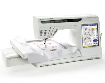
My mother was using the Husqvarna Viking Designer SE Sewing Machine but it started to exhibit some strange failure modes.
Most of the time when powered on the machine would simply lite the back light of the LCD and basically do nothing. Occasionally (as reported by mom) the machine would turn on like normal after turning off and on the machine several times. I was not able to reproduce this (prior to taking it apart).
My mother took it to the repair place and they wanted to replace the main board the power supply and the LCD for a whopping $2000. Instead of settling for this she just got a newer bigger and better machine for 5 times the cost of the repair.
Step 1: Power
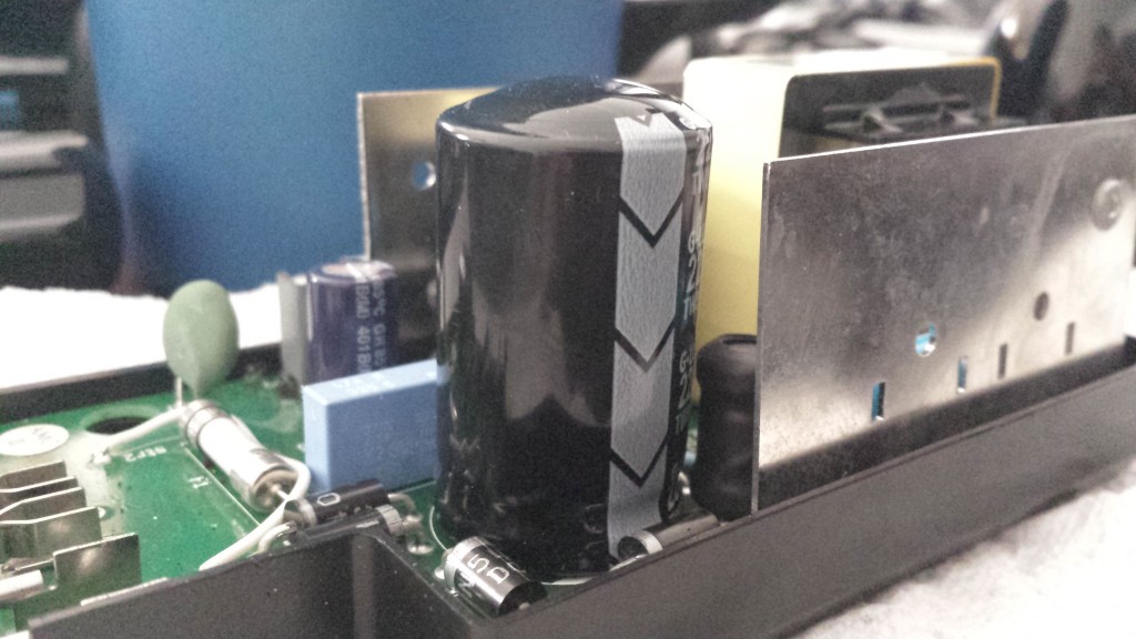
I decided to start with the obvious first, power. This machine has what looks like a specific made power supply. I cracked it open an haha the telltale bulge on the main filter cap.
Some ordering and a bit of soldering later and …..
no dice 🙁 same problem.
Not entirely sure if the cap is dead or almost dead. It is suppose to be 220uf and it measures 207uf which is inside the +-20% that it should be. Its got the bulge so it cant be far from failure.
Step 2: Classifying the Intermittent Failure
This step was tough. As all intermittent failures go they are hard to nail down. I tried to no avail to get the darn thing to actually power on in the way my mom reported it would (reason why down below). On, off, on, off through many cycles. It was always the same thing back-light lit but nothing else. I tried removing various connection to its plethora of sensors and motor controls but nothing worked. This step admittedly took the longest and I ended up shelving the project for 4 months due to frustration and lack of progress.
Step 3: Heat
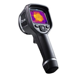
So I got a bit more money back from taxes that I was expecting and I splurged on something that I was wanting to get for a while the FLIR E4.
I got this lovely thing to help with this specific problem and to help fix my drafty house (and also toy around with cause it cool).
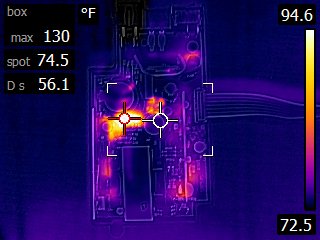
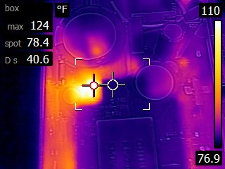
I started by poking around looking at the power supply thinking that there may still be an issue.
The was a hot spot but it tuns out the component making the most heat was an inductor which is sort of as you would expect.
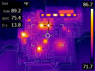
Next on to the main board.
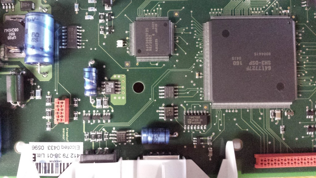
The red cross hairs and the spot to the left are motor controllers. The series of 6 spots above are also motor controllers but they are obscured by a copper heat spreader. I noticed one of the motor controllers was warmer than the rest so I examined it further.
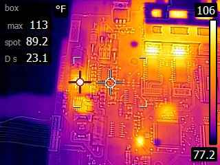
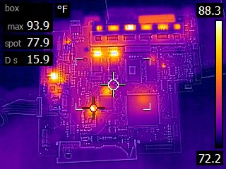
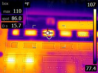 After closer inspection and more time to warm up it appears that it is no hotter that the other (un-shielded controllers). I next moved on to two other noticeable hot spots. the first one is a 24v to 5v dc to dc step down.
I measured out the voltages and everything seemed to be in order. The next was also a regulator its a 3.3 to 2.5(adjustable).
I checked the voltages here too and everything was spot on. A bit frustrated at the prospects of hitting another dead end I thought about the intermittent problem again. If the problem was heat related that could explain why flipping the switch a few times made it work. Maybe it was “warming up” to make it work. This is odd to me and I have never heard of this. I am familiar with “cold solder joints” but they tend to manifest in the opposite, works cold and fails when warm.
To test the warm-up hypothesis I pulled out my smd rework heat gun and set it to its lowest temperature 100c. I went for broke and started warming up everything on the board to see what would happen. After only a few minutes of this, success! The damn thing powered on. This theory also makes sense why I never got it to work when trying to get it to ever work. The bulk of my tests were with the cover off which reduced the heat load on the board.
The warm-up theory holds water yeah me!
It only took a few more minutes to narrow down the warm up spot to the second hot spot detailed above. I was able to reliably reproduce the resolution. From a cold board I would hold a 100c heat to that area for 6-10 seconds and the machine would power on every time.
Ok so now what? I started by taking a closer look at the IRU1209CS regulator thinking it may be faulty. I had already measured the voltages and they seemed fine. I started thinking that I may need to order a replacement but after some digging it appears that it is no longer available. At this point I was thinking great this thing may never work again.
Frustrated with replacing the regulator I moved on with a great epiphany; If this spot is so warm that electrolytic cap is mighty close to it. I did some scrounging and I found a sort of compatible fit in my collection. I found an radial 10uf 62v electrolytic capacitor. I had to bodge it in a bit since I need a axial cap but I was able to just barely stretch it in there. Low and behold the thing powers on the first time every time.
Problem solved.
Step 4: More Details
So I have never heard of a cap failing when cold (maybe I am just a novice). So I decided to get more information. First I measured the cap.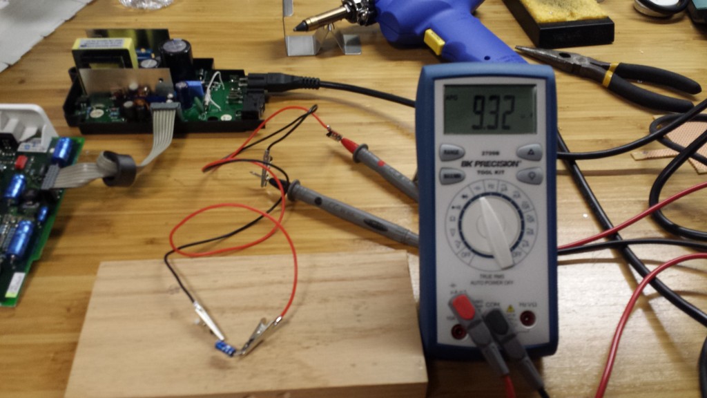
Err 9.32uf (at room temperature)…. that does not seem too bad since it is well within the +-20% (8uf to 12uf). So what then does warming up a capacitor do? Lets see.
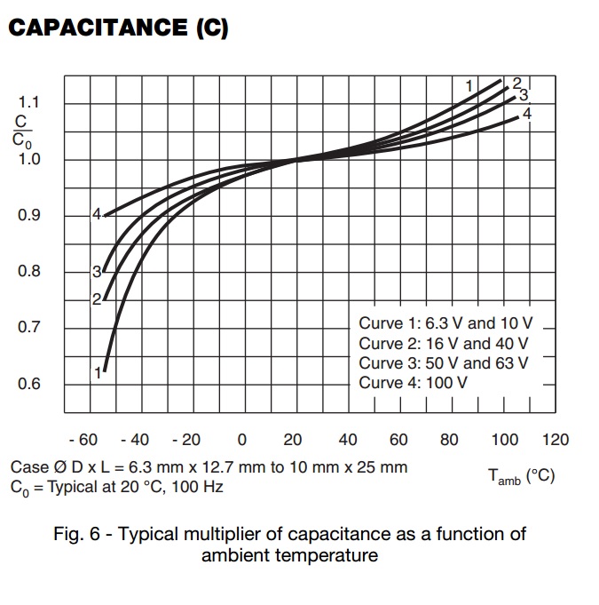
As you can see heating it rapidly increases the capacitance from 9.32uf to 10.28uf and then quickly drops back down. This is odd to me. Is it some how getting the electrolyte working better? I had no idea of this behavior of capacitors. I looked as the datasheet for this cap and found this graph.
As you can see that yep, going from 20c to 90c (aprox) will increase the capacitance by a factor of 1.1 which is almost exactly what I saw in the video. Ultimately this all means that the cap even though it was technically in spec was still not up to the task. Or could it perhaps be that something else is going on somewhere else that needs this cap to be closer to 10uf. Only time will tell as I have not reassembled the thing to see if its fully functional.
Conclusion
There you have it I seem to have fixed the problem, sort of saved money (potential resale value) and most important learned something along the way. And bonus, if you are reading this maybe you learned something also or maybe just had and enjoyable time.

