Free Sample – Ti SimpleLink Wi-Fi CC3000

On occasion I sign up for free samples when the some of the sites I follow (http://hackaday.com/, http://dangerousprototypes.com ) report on them.  And on occasion I actually receive them.  This time I got a sample of the Ti SimpleLink Wi-Fi CC3000 http://www.ti.com/product/cc3000.

The TI CC3000 module is a self-contained wireless network processor that simplifies the implementation of Internet connectivity. TI’s SimpleLink Wi-Fi solution minimizes the software requirements of the host microcontroller (MCU) and is thus the ideal solution for embedded applications using any low-cost and low-power MCU (ref. http://www.ti.com/product/cc3000)

The module does have a somewhat difficult footprint to work with for a non-professional:

cc3000 footprint

cc3000 footprint

But they have posted schematics for a eval board design.  Hopefully I can take this and modify it to something that I can etch myself or possibly even get professionally done.  There seems to be some great resources on the Ti wiki http://processors.wiki.ti.com/index.php/CC3000.  At $10 per unit (at 1ku) I do not think it will be long before we see lots of these available for all sorts of hacker projects considering adding Wi-Fi to a project still costs $30-50.

2013-03-29_07-08-22_469 2013-03-29_07-08-41_537 2013-03-29_07-09-33_719 2013-03-29_07-10-02_554

Quick Update – Filastruder KickStarter

I just wanted to post a quick update on an interesting development.  I backed a kickstarter project http://www.kickstarter.com/projects/833191773/filastruder-a-robust-inexpensive-filament-extruder that extrudes 3dprinter filament from bulk material. The advantage to this is that it makes the filament for 1/6th the costs of what vendors are currently selling it for.  It also gives the added advantage that custom colors are possible.  I backed a fully assembled model since at the time the kits were sold out (they since added more kits).  Simple calculations are as follows $300 filament extruder $5/kg PLA pellets (est.) and $30/kg for premade. This makes the extruder pay off after only 10kg of filament.  That seems like a great deal! Ok, yeah, yeah that does not include the price of electricity and what not but it does make it really cheap.  Even if it takes 15kg to pay it off its still worth the price.  Here are some pictures I swiped from the kick starter site of the prototypes:

Filastruder prototypes

Filastruder prototypes

PCB Etching – Update 1

Two posts in one night… man when it rains it pours I guess…

I had another update on the PCB etching.  Once again we failed.  This time I ordered some Toner Transfer Paper http://www.amazon.com/Toner-Transfer-Electronic-Prototype-Sheets/dp/B00B0ZDXB2/ref=sr_1_1?ie=UTF8&qid=1363659597&sr=8-1&keywords=toner+transfer+paper.  The failure was not with the paper though.  My friend tried to print the schematic onto the paper and the toner would not stick.  Most of the toner came right off.  Frustrated I call another friend with a laser printer to try his and it was slightly better but still terrible.  Finally I took the output pdf to work and printed there and finally success.

The only thing that I can think is that both printers that failed were color laser printers.  The first was a konica minolta 2500 and the other was as xerox 7500 ??? (Ill get the exact number soon).  The one at work was not a color laser just good ol b&w Xerox Phaser 3600 http://www.support.xerox.com/support/phaser-3600/support/enus.html?operatingSystem=winxp&fileLanguage=en.  The jury is still out on why the toner would not stick more investigation is required I guess.

Here is the schematic printed on the TTP ready from transfer.  Attempt number 3 will be coming soon.

Bottom

Bottom

Top

Top

3D Printed Case for the TrH Meter – Update 1

I am happy to report success with creating a 3D Printed Case for the TrH Meter from previous posts.  This is the first 3D object that I made from scratch!  I published it on the Thingiverse http://www.thingiverse.com/thing:62990.  I must say that once I watched the Ben Heckendorn video the design became really easy.  I highly recommend the video http://i.materialise.com/blog/entry/tips-and-tricks-by-ben-heck-how-to-use-autodesk-123d-design if you want to do a box similar.  My total design time was about 4 hours and the print took 2 hours (top and bottom).

I did also design another case/box for a friends electronics project (maybe another post on that one too) and that only took about 2hrs.  I suspect the next one will be even faster.

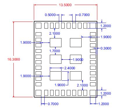
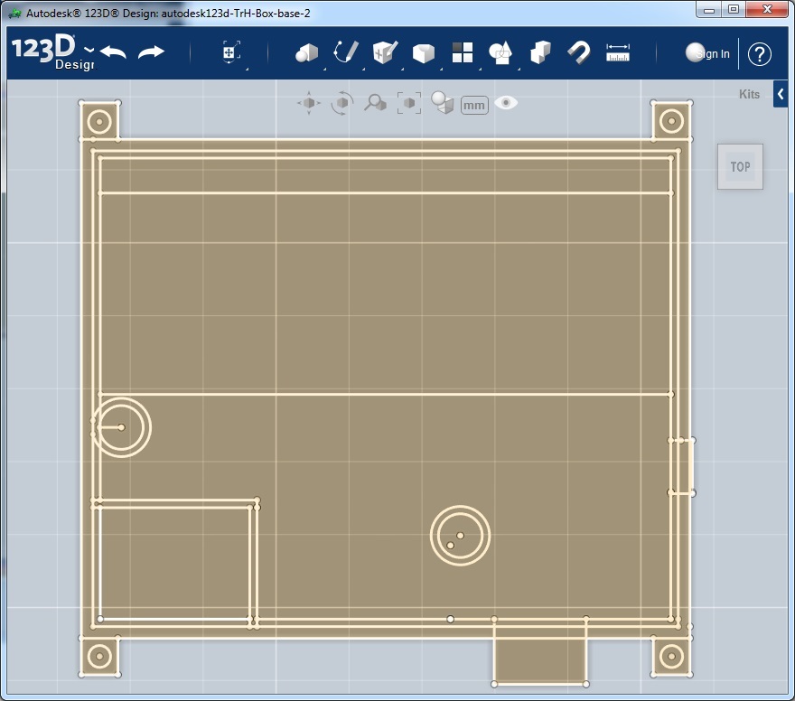
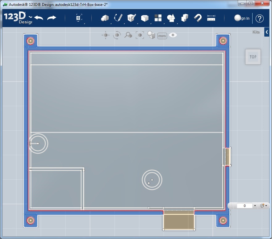
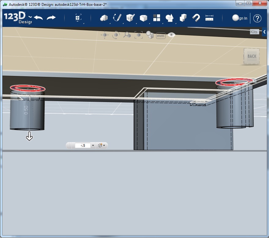
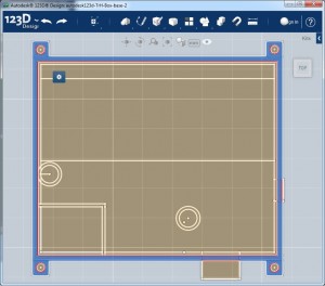
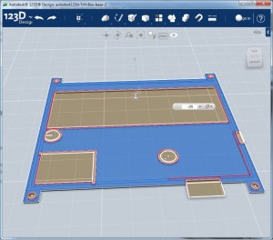
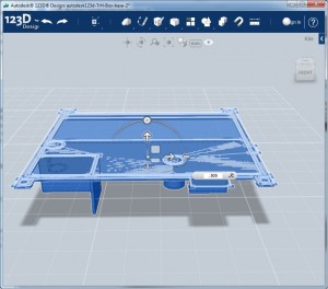
Here is a screenshot of my base.  This is all the dimensions of all the features of the box.  Think of this as a 3D object that is squished and flattened into a 2D object.  Make sure that you save this off because you will need it again for the bottom.  If you find you need to make changes it’s a good idea to save off back to the base so that you are working off the same file for the top and bottom.

2DBase

The drawing is relatively easy to do using the Sketch (2D) menu.  This is just a series of squares lines and circles

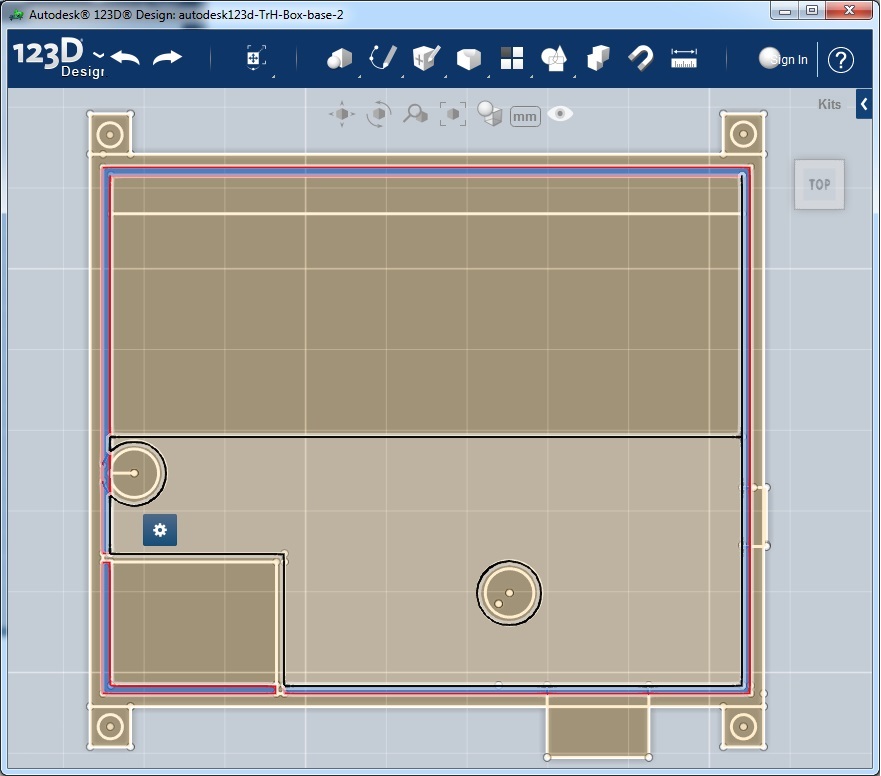
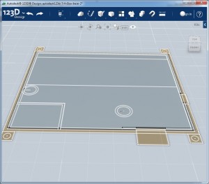
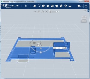
For clarity I thought I would point out some of the features of this base.  There is an “air” space between the PCB and the walls of the box I have highlighted them here:

AirSpaceBorder

Highlighted here are the outer wall that will extruded up to make the sides of the box

OuterEdges

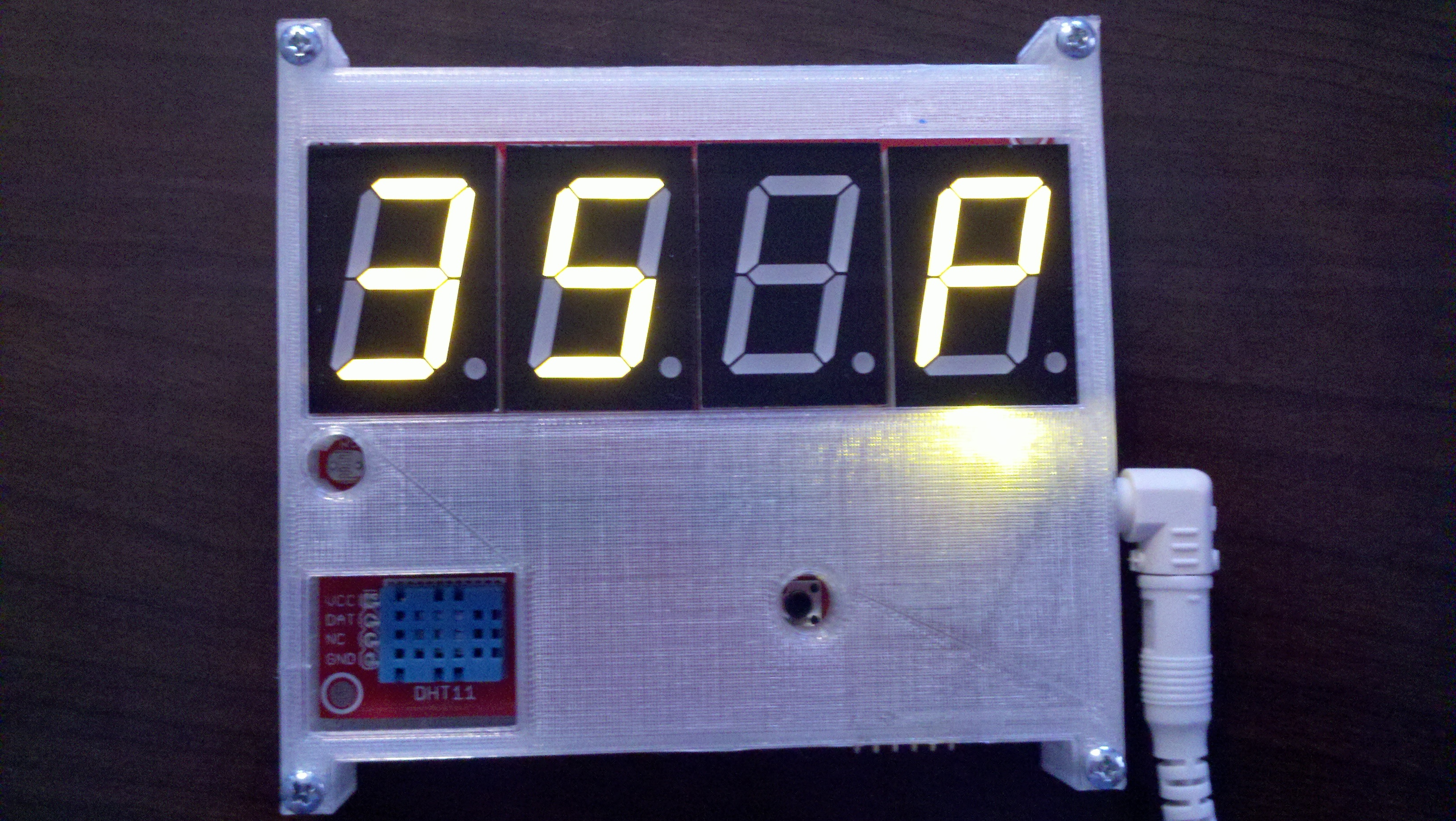
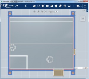
The holes in the middle are for the reset button and for the light sensor.  The 7 seg displays will dim when it’s dark so you are not blinded by them.

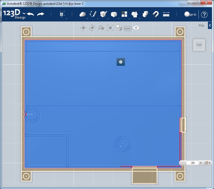
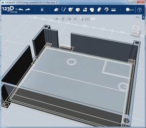
Step two is to start the extrusion.  You need to extrude common components together.  This does take a bit of thought since you can only extrude a part once (which is no big deal).

Here I am extruding the underside of the PCB

BottomExtrude-1

And here is the result.  It’s difficult to see but this is a 3D of the base that is .05 inch tall

BottomExtrude-1a

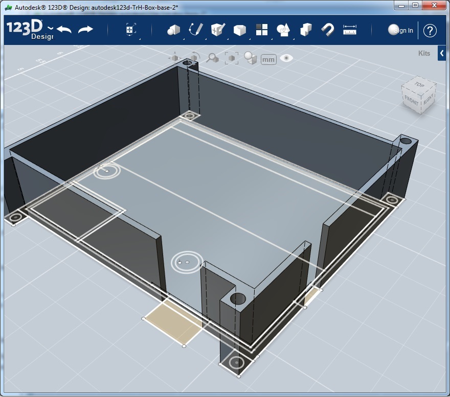
The next step is extruding the sides of the box.  Notice that I do NOT have select two pieces on the side as those are the bottom part of the holes for the power and serial connection which I want to be a different height.

BottomExtrude-2

Now it’s starting to look like a box

BottomExtrude-2b

And finally with the pieces under the holes extruded.

BottomExtrude-3a

We can we can send this to the printer by selecting everything and exporting it to .stl.  And while that’s printing we can move on to the top.

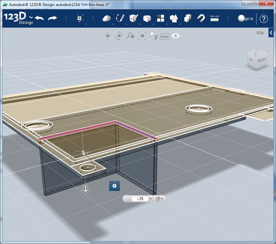
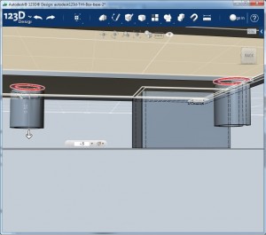
Start again from the base, this time we are going to extrude in the negative (-) direction.  Essentially extruding down towards the bottom (which extruded up towards the top).
Here is a shot of my first print where I forgot to extrude down.  You can see that the protrusions are sticking up from the box.  Oops.

oops extruded in the wrong direction

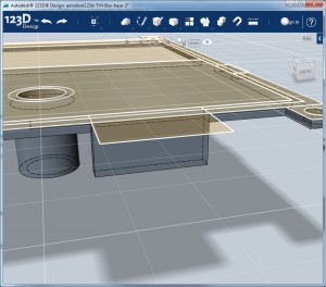
Here is first extrude

TopExtrude-1

Next is a small area that encloses off the temperature and humidity sensor from the other components and leaves it open to the front from measurement. Remember when entering the extrude dimension to add the first extrusion to the distance you actually want it to protrude.  For example my top most piece is .05 inc thick and I want the protrusion to stick down .5 inch you need to extrude to .505 to get the correct depth.

TopExtrude-2

Next I extrude the holes that surround the reset button and the light sensor (that dims the 7 seg displays when it’s dark)

TopExtrude-3

Then finally the top part of the hole to make the serial connection just a small sliver of a hole on the side of the box.

TopExtrude-4

Now we need to move the thing back to the ground plane.  To do this select the whole thing and click move.  Grab the up arrow on the movement directional and drag up. This will allow you to type the number in.  This number is the maximum amount you extruded into the negative.  In my case it was .505.

TopMoveUp

Then we need to rotate the thing 180deg for printing.  Select the whole thing again and click move.  This time grab the circle above the up arrow and rotate it.  Again the box will appear to allow you to type 180 deg.

TopRotate

Sweet! Hopefully by now the bottom is done printing (mine took 1h 23 min).  Peal that thing off and send the top to the printer.

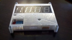
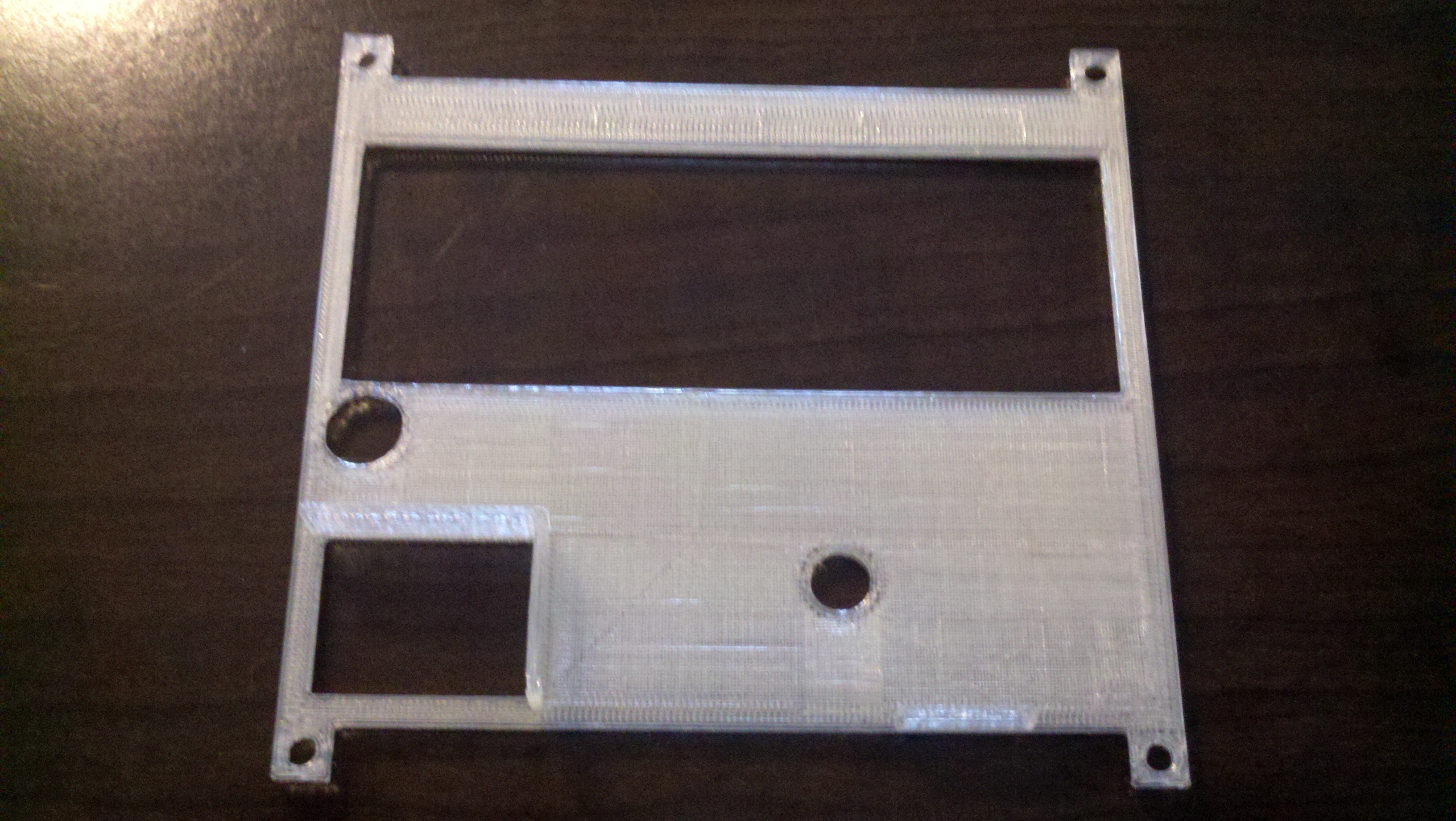
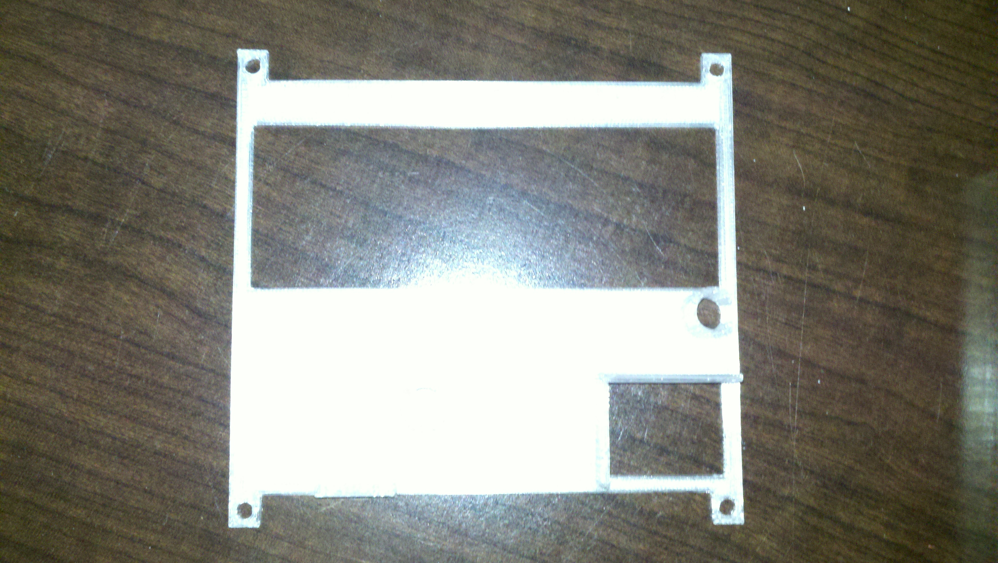
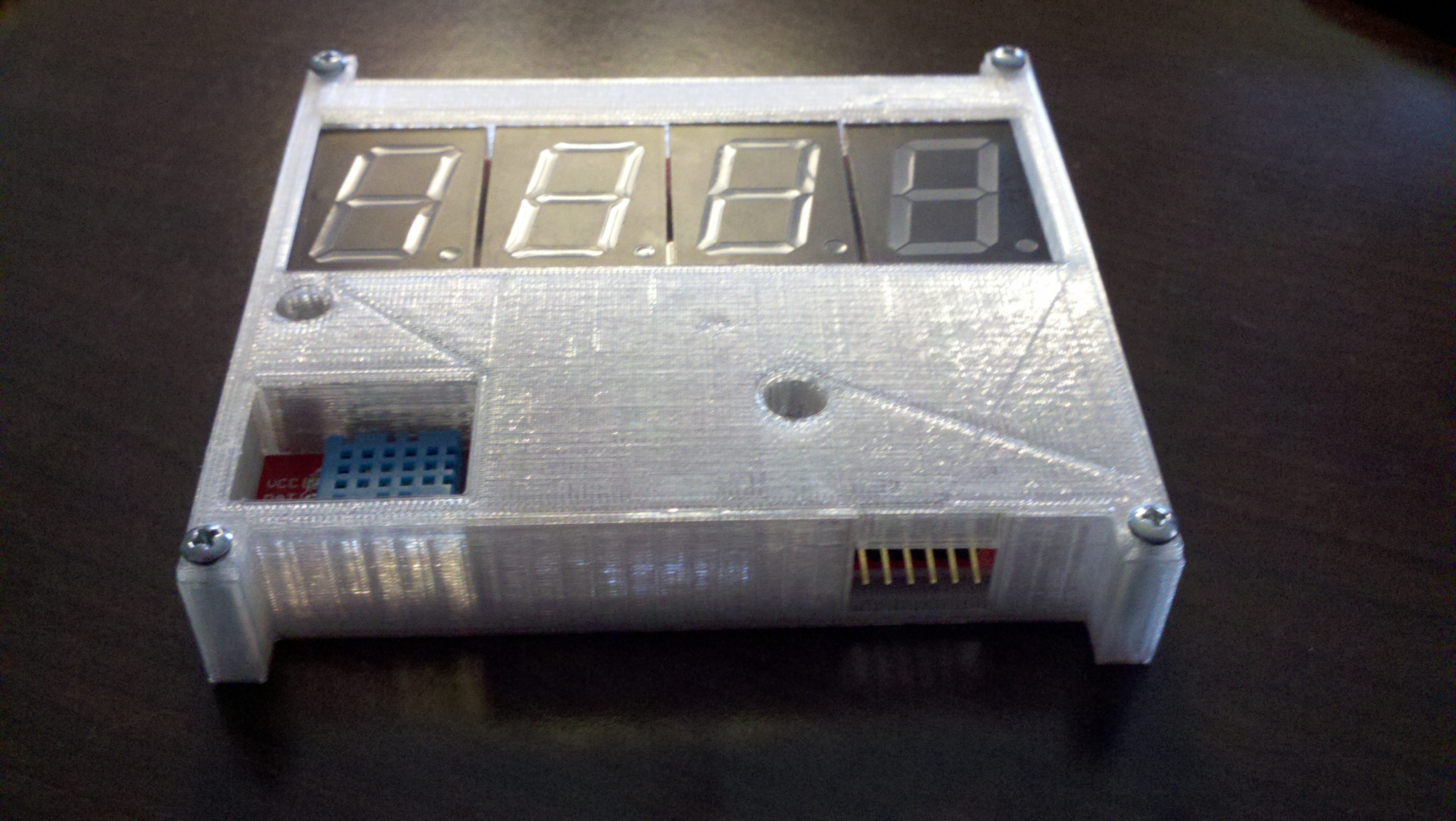
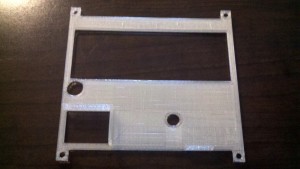
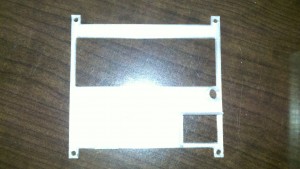
Here is the correctly printed top

2013-03-17_17-53-48_975

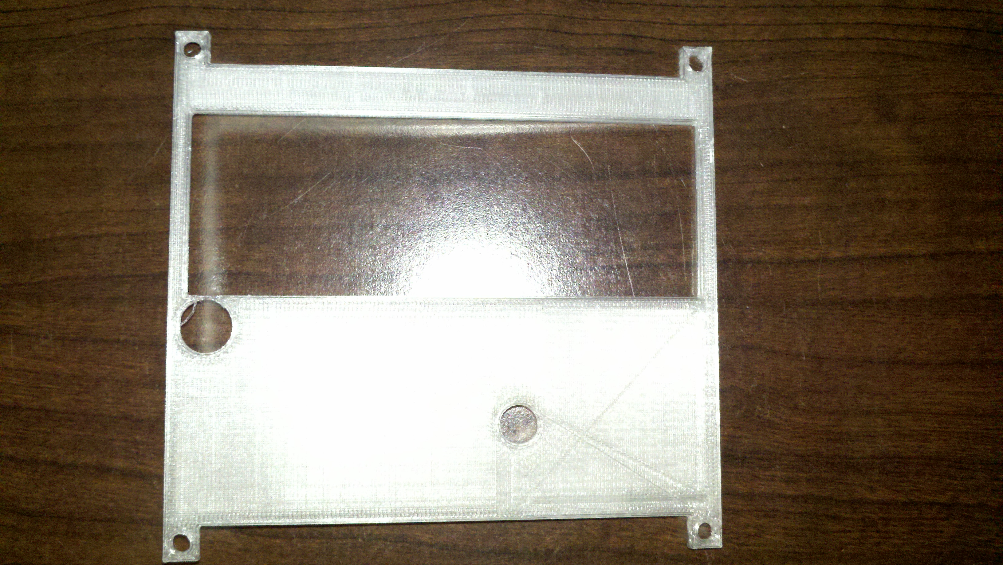
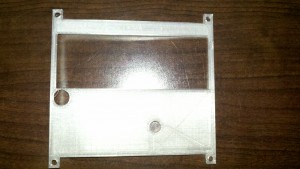
And here is bonus mistake again on the top.  I forgot to leave out the hole above the humidity sensor.

oops 2

The top printed in 37 mins.

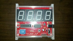
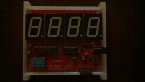
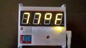
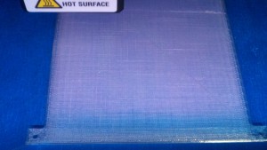
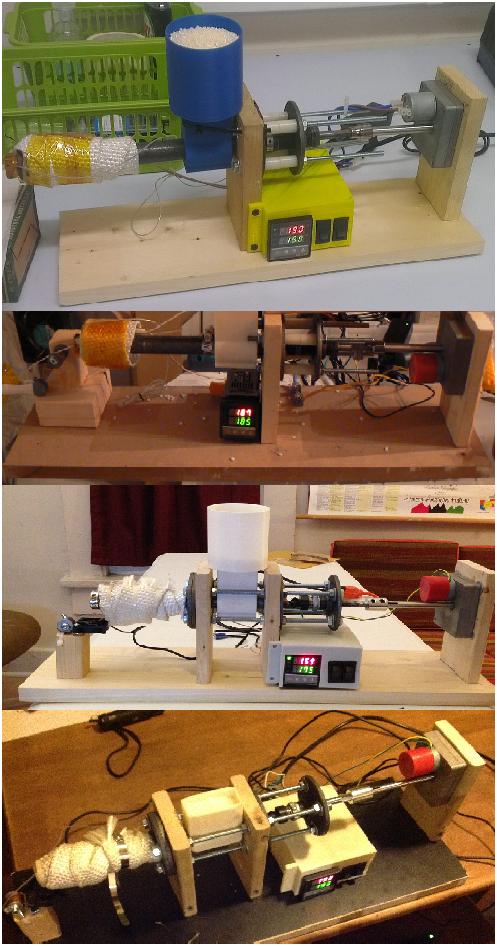
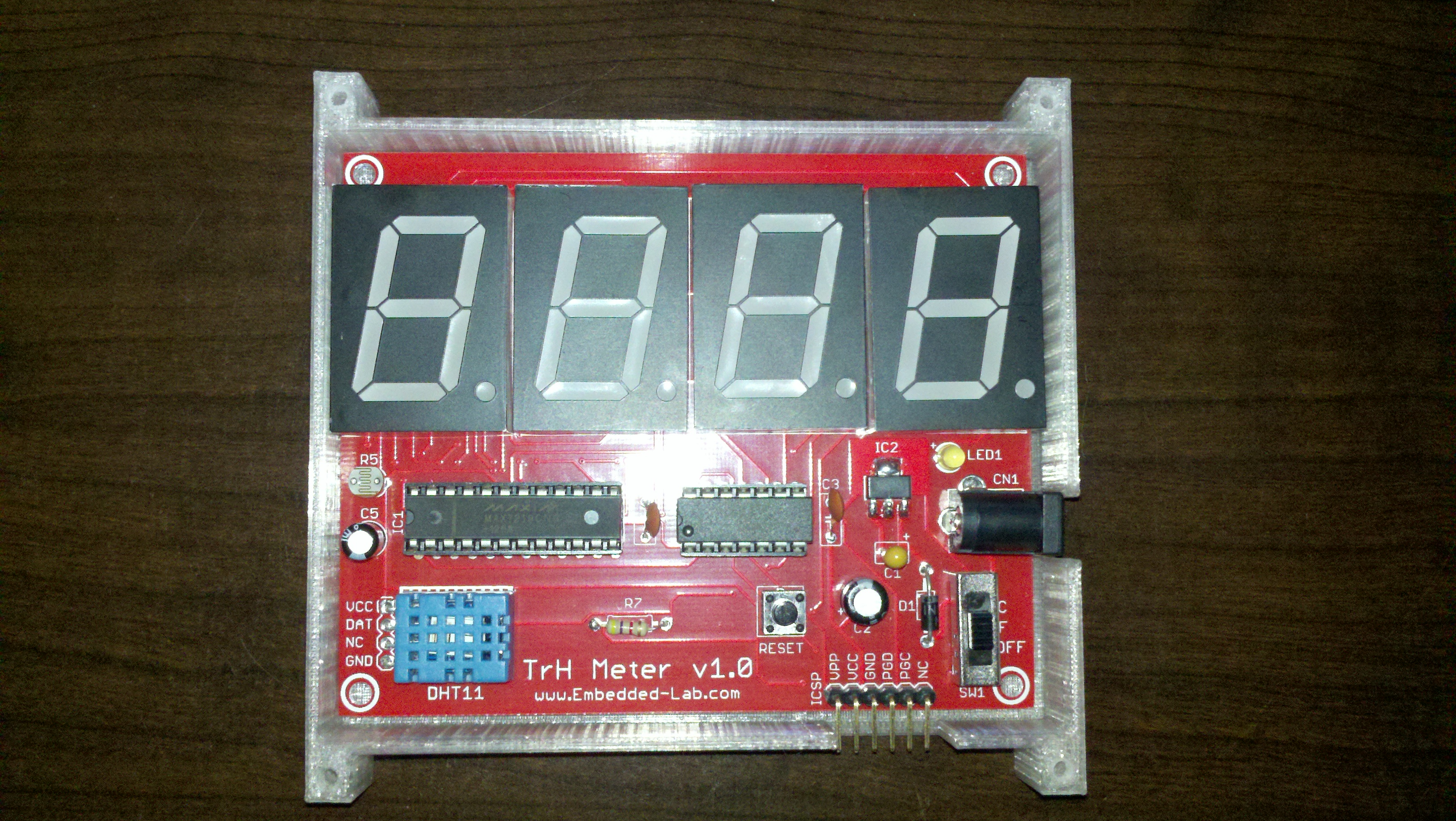
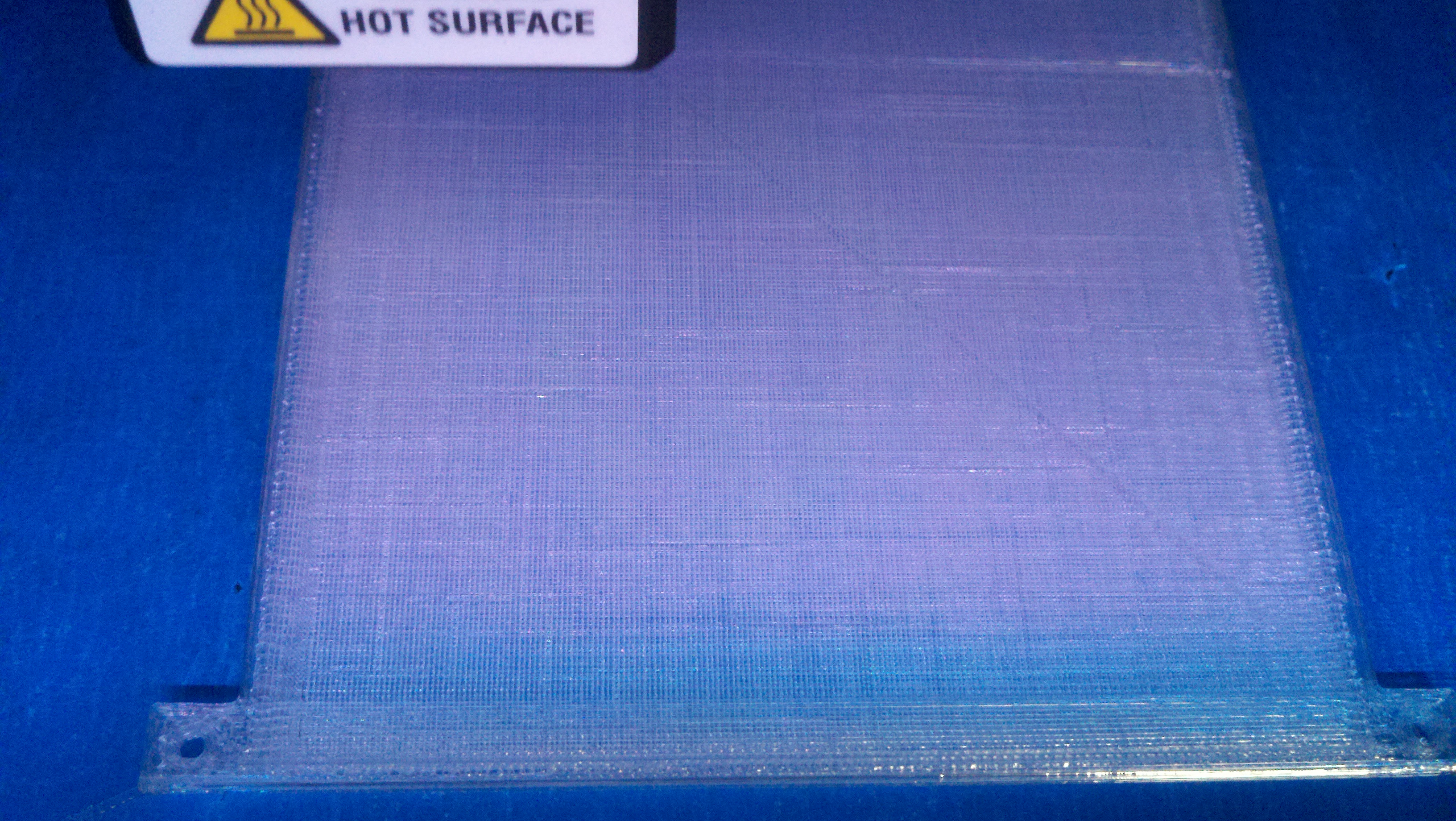
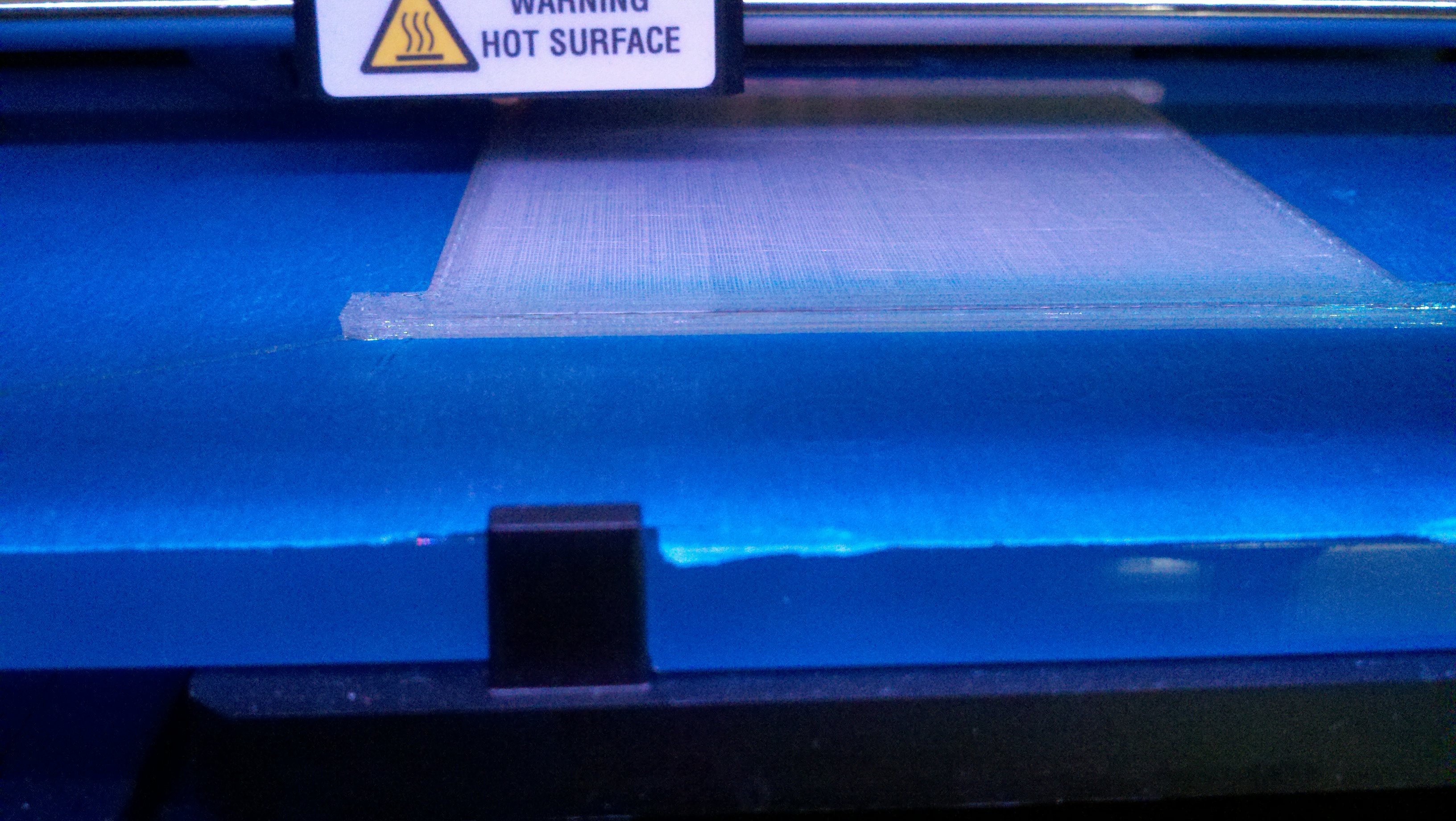
Here are some pick of it printing and the final product.  Don’t forget to post it out on the Thingiverse.

2013-03-17_17-53-32_209 2013-03-17_17-53-23_218 2013-03-17_17-52-01_901 2013-03-17_17-51-43_996 2013-03-17_15-50-39_430 2013-03-16_12-18-06_163 2013-03-16_12-17-57_813 2013-03-16_12-17-47_856

More posts comming soon

I just realized that it’s been quite a while since I posted here.  More post are coming soon.  I have been doing some interesting things since my last post here are things that are coming soon.

Capital News Paper

I have been contacted by a reporter from the local news paper.  He wants to do a story on 3D printing which I think is fantastic.  Hopefully I can provide some insight in to how to get started with 3D printing.  This is all still preliminary since I have no idea on what to expect out of this.  More information as soon as I get it.

3D Printed Case for the TrH Meter

I have been trying to design a case from scratch and I have had little success.  I have tried quite a few 3D design tools and none of them live up to my expectations.  A friend recently send me a link to yet  another Ben Heckendorn video where he creates a raspberry pi case http://i.materialise.com/blog/entry/tips-and-tricks-by-ben-heck-how-to-use-autodesk-123d-design after watching this I got some ideas on how to use Autodesk 123D in a different way than I was using before (using the extrude method).  I will post a full tutorial on the creation process once I am done.

PCB Etching

I have been working with a friend to etch a PCB using the toner transfer method.  This is our first PCB that we have etched from scratch so it’s taking a bit longer than I expected.  Our first attempt did not meet our expectations and we decided to regroup and get better equipped.  As soon as we try again (maybe this weekend) I will post our results.  Here is the PCB we chose: http://vonkonow.com/wordpress/2012/10/nanino-the-diy-friendly-arduino/.  We did modify the schematic some.  We added back the voltage regulator and resided some of the holes for easier drilling.

Simple Robot

I have done a bit more work on my mapping robot (that I have been almost never working on for over the last 10 years).  I added finally added the dual serial motor controller that I bought last year.  I make no promises on this project as at this point it has an estimated completion time of NEVER (+/- 5 years).