So what are you to do if you have only one print head like my replicator 2 has but you want to print two colors? Some may give up and say “ya just can’t”. I have already show that is not entirely true. Remember my two color business cards? http://www.3dprintmd.com/print/printed-business-cards/
Ok well some may say that this is cheating and this is not really two color printing. It is merely using z-stop and changing colors. Ok fine I get that, and I was not really satisfied with it either.
Lets take this concept one step farther. How about printing around another object instead of on top of it? Turns out, yep, you can do that that too. It turns out to be relatively easy but with a ton of caveats.
First a word of warning. If you do not pay close attention to what you are doing you could damage your printer. Printing on top of another printer is not recommended for the inexperienced and it could cause your print head to crash into the first print or worse strip a belt or cause other damage. I am not responsible for if you break your things.
Now with that mombo jumbo is out of the way…
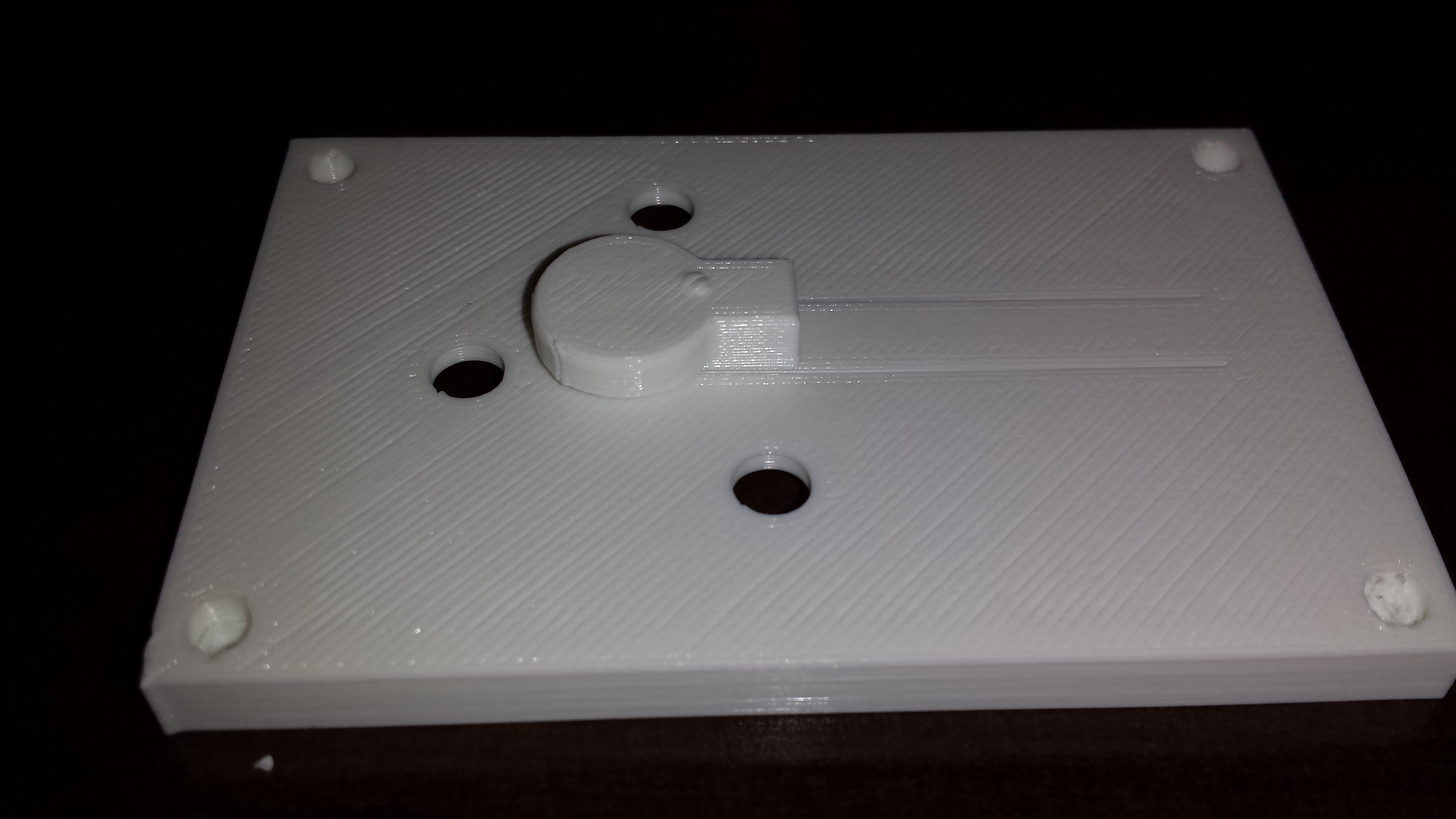
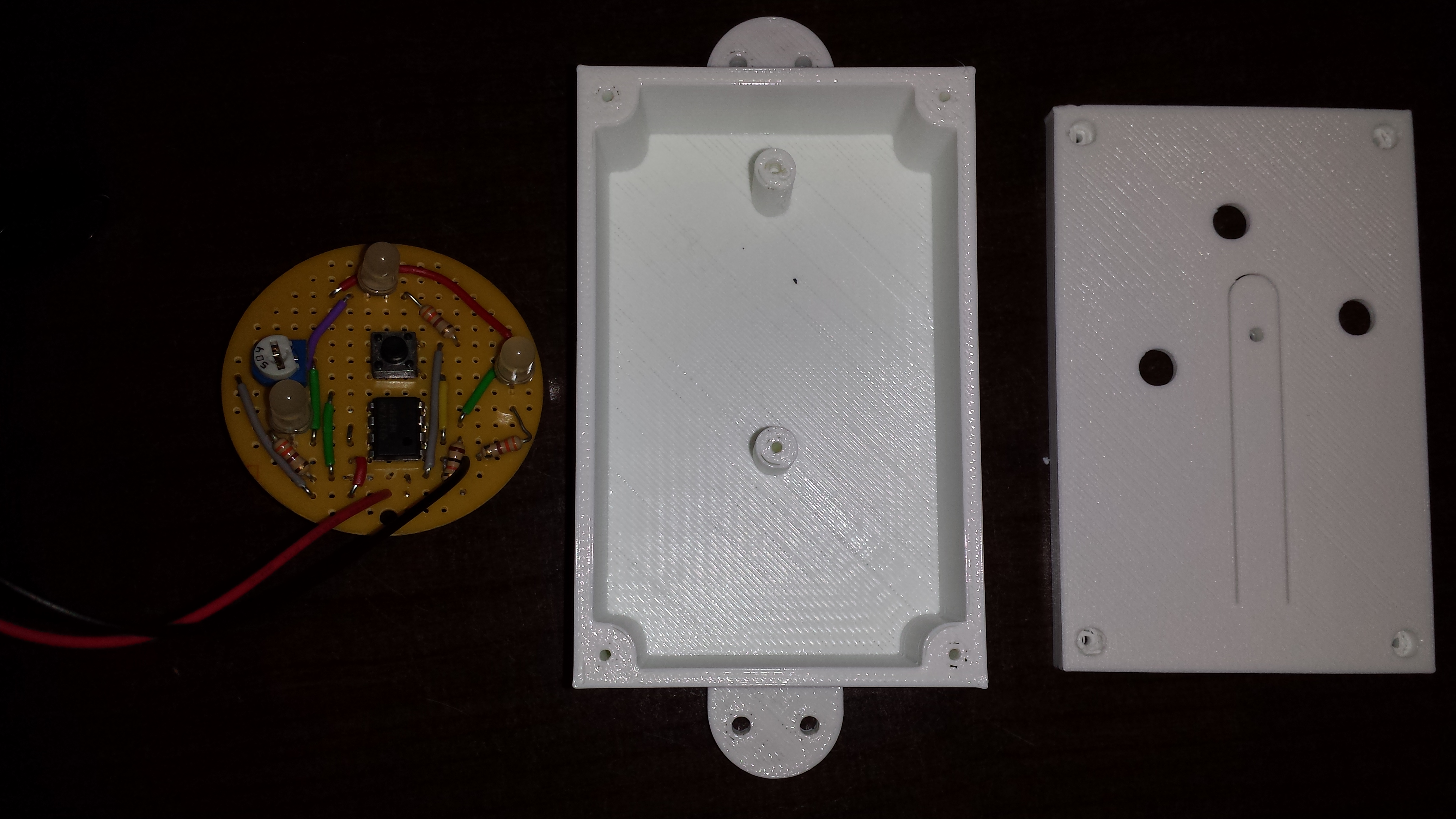
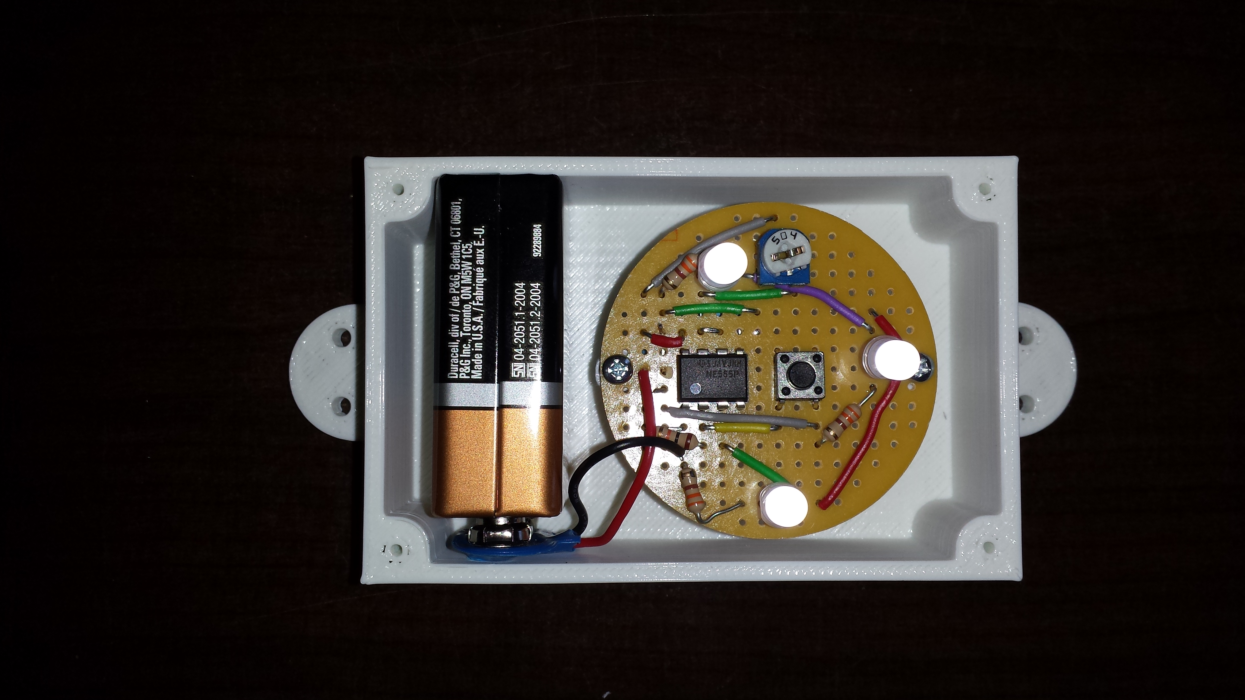
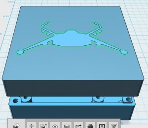
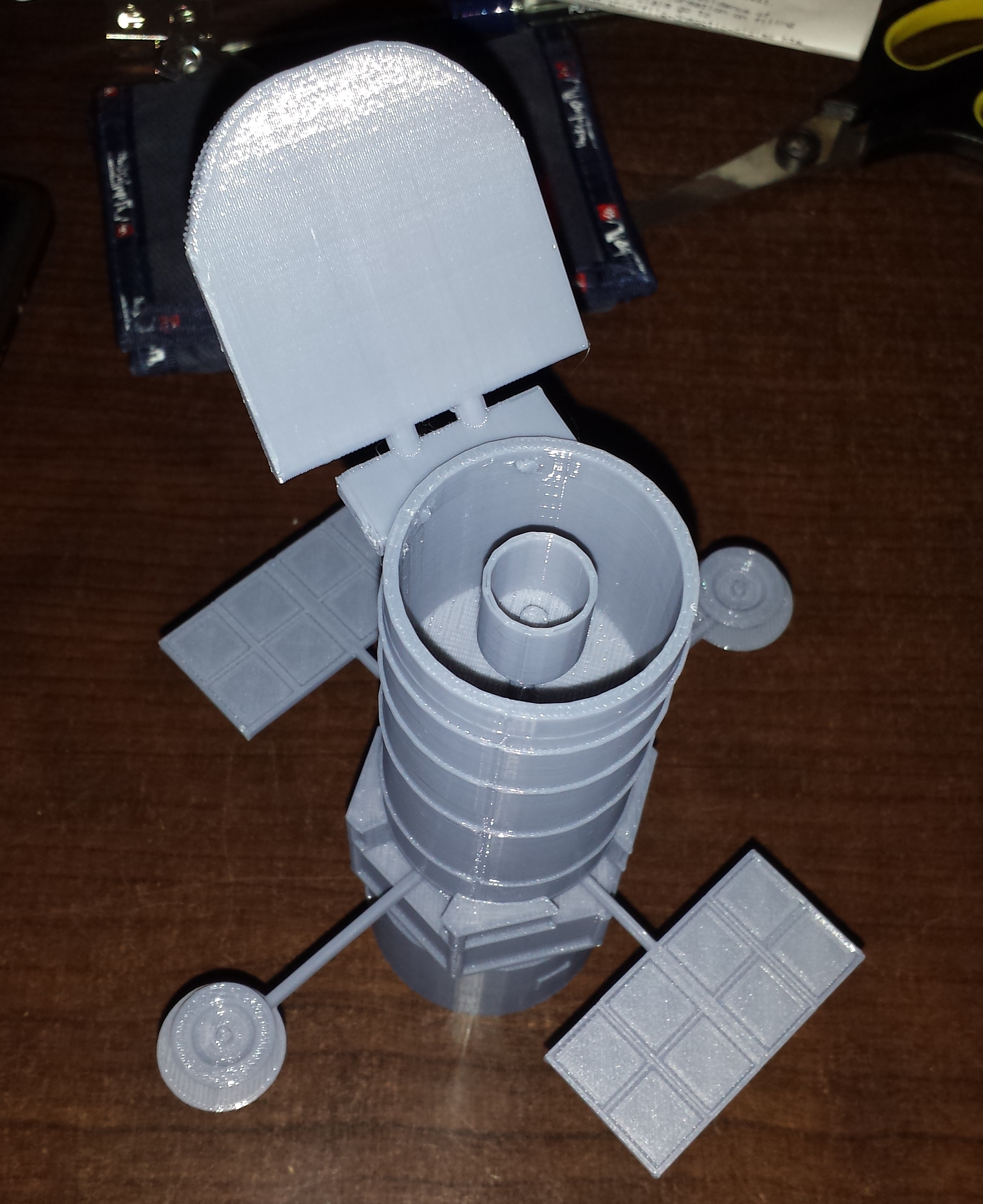
Here is the goal: I am printing a case for a usb adapter for the Old skool Sidewinder Joystick (http://www.descentbb.net/viewtopic.php?f=8&t=19061&sid=3da4f9e4089d6418b7a500aeab2aaa0c&start=160)
We didn’t want just any old case naw, that would be too easy. How about one with a logo inlaid into the top. Wells that’s easy enough if you have a two head printer. But you only have one print head? Well then challenge accepted!
Whats the problem you say with just printing one piece then printing another around it you may ask? Well the problem comes when the second piece is printing the slicing engine does not know that it should not crash into the piece already printed. Its needs to stay out of that area but there is no way for it to know how to do that. It turns out that there is a happy accident awaiting to be discovered.
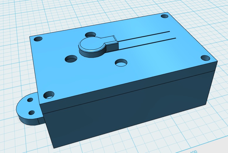
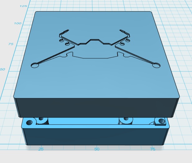
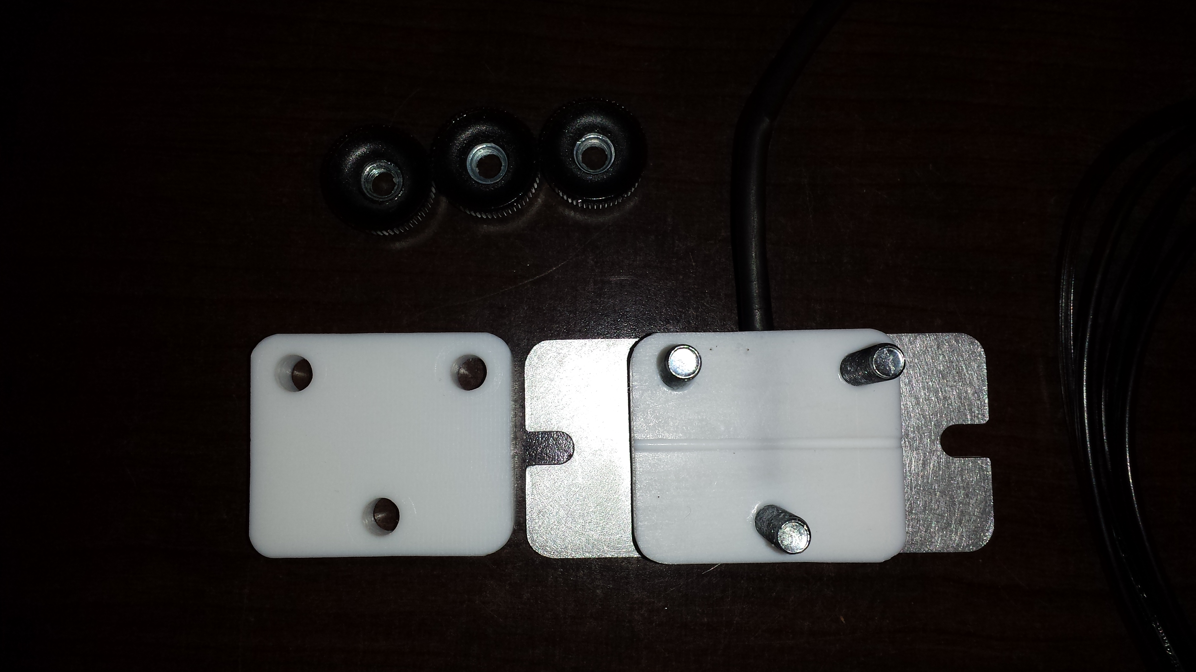
First prepare the model. This is easy enough.
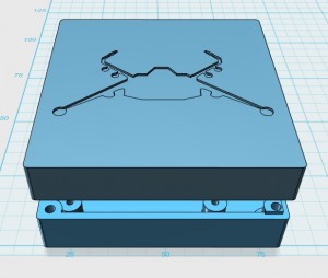
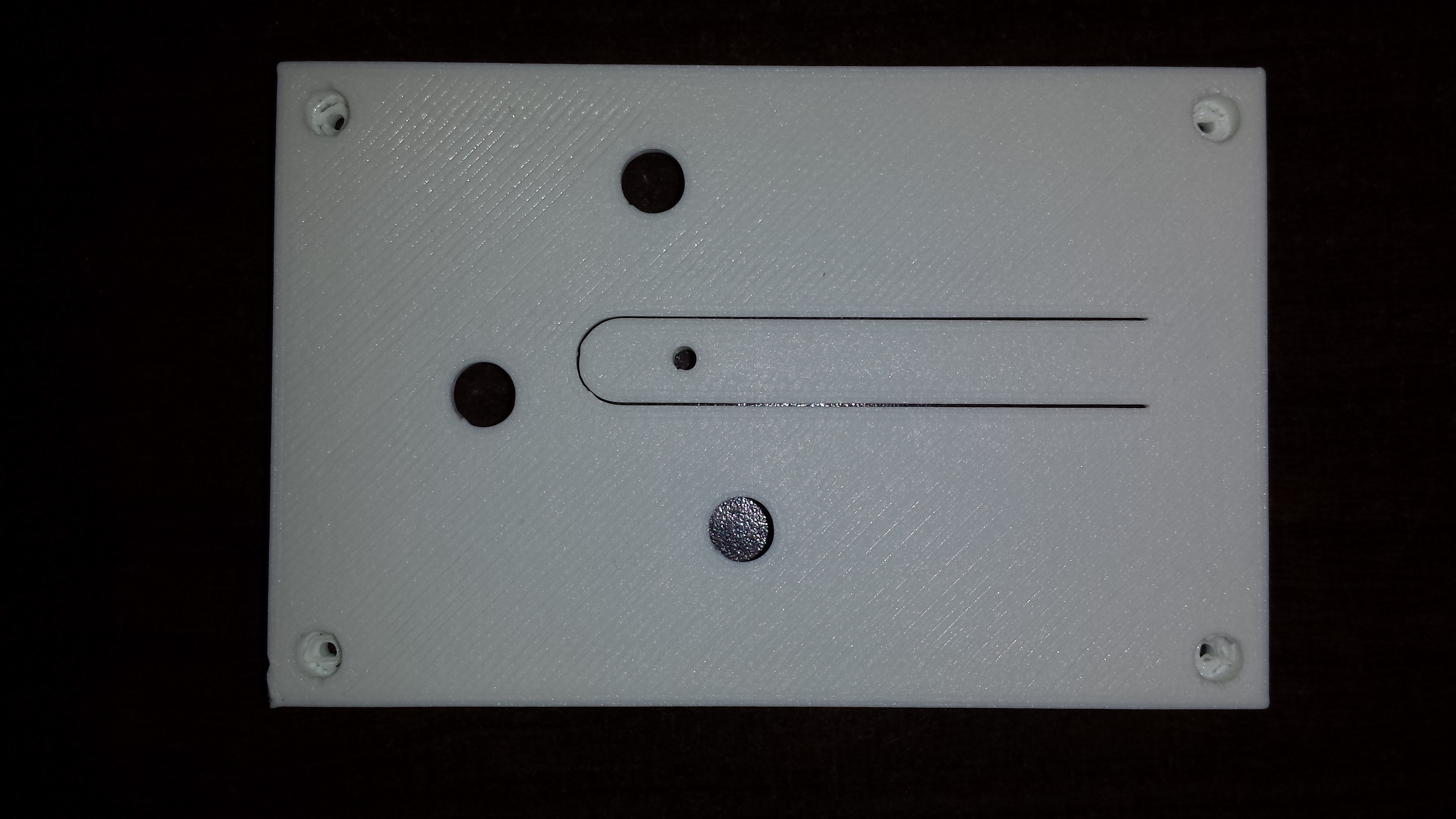
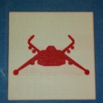
Top With .6mm deep hole in the shape of the logo
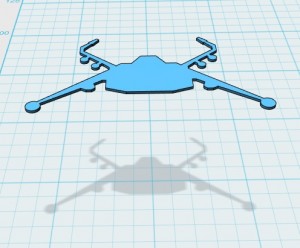
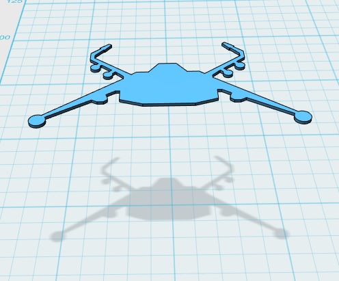
Logo .6mm Thick
Top and Logo aligned
I have only done one of these and it is possible that I just simply got lucky with the design. The design needs to be simple and should not have any holes in the middle of it. Other design limitation may exist but I have not done enough of them to know for sure. The design will play out in the next several step to see if its a viable option. Please note that the inlay is exactly .6mm thick. I will be printing with .3mm layer height and this will amount to exactly 2 layers being printed. I would NOT go any higher than this. The nozzle is an upside down cone shape and therefore gets bigger the farther away from the build pate you go limiting how close you can get to the first print.
Set up the slicer.
Here is what NOT TO DO and the reason why
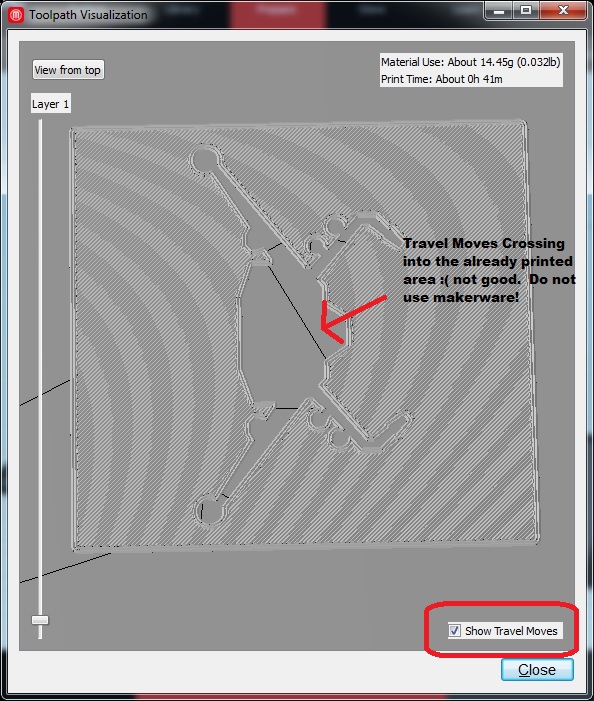
Makerware is not an option for printing since the tool path algorithm likes to use any empty space round the object being printed.
If we slice with makerware there is nothing you can do to get the travel moves to not cross into what would already be printed. Remember that we will be printing the logo first and the box around it must not cross into the logo area. Otherwise, the print head will crash into it.
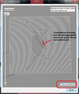
Makerware is a no go. Travel moves cross into the logo area.
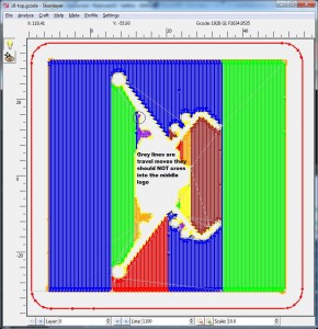
So what can we do instead? ReplicatorG to the rescue. I know what your are saying ugg not RepG that thing is so hard to understand and confusing. Yea I get that too but in this case there is a happy accident in the slicing engine that is going to save the day.
It turns out that when RepG slices it tends to only follow the perimeter (in this case interior) of the object when doing travel moves. Why it does this is somewhat of a mystery to me but, at least for this object it works out perfectly.
First edit your slicing profile to show the tool paths (or to make it easy you can copy mine. Replicator 2 – 340 micron)
In order to make sure that the travel moves don’t go where they should not go. Go to the Craft tab and activate Skeinlayer
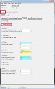
Activate Skeinlayer
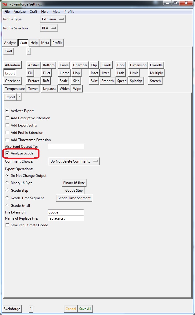
Then go to the Export tab and enable Analyze Gcode

Analyze Gcode
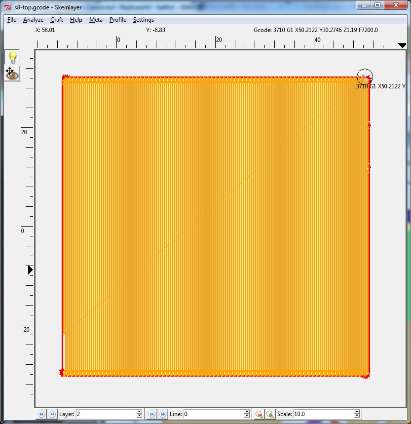
Now when you slice you will get a Skeinlayer popup.
When you open you stl files make sure that if you change the location on the build platform you make the exact same changes to both the logo and the top. These parts must be exactly aligned.
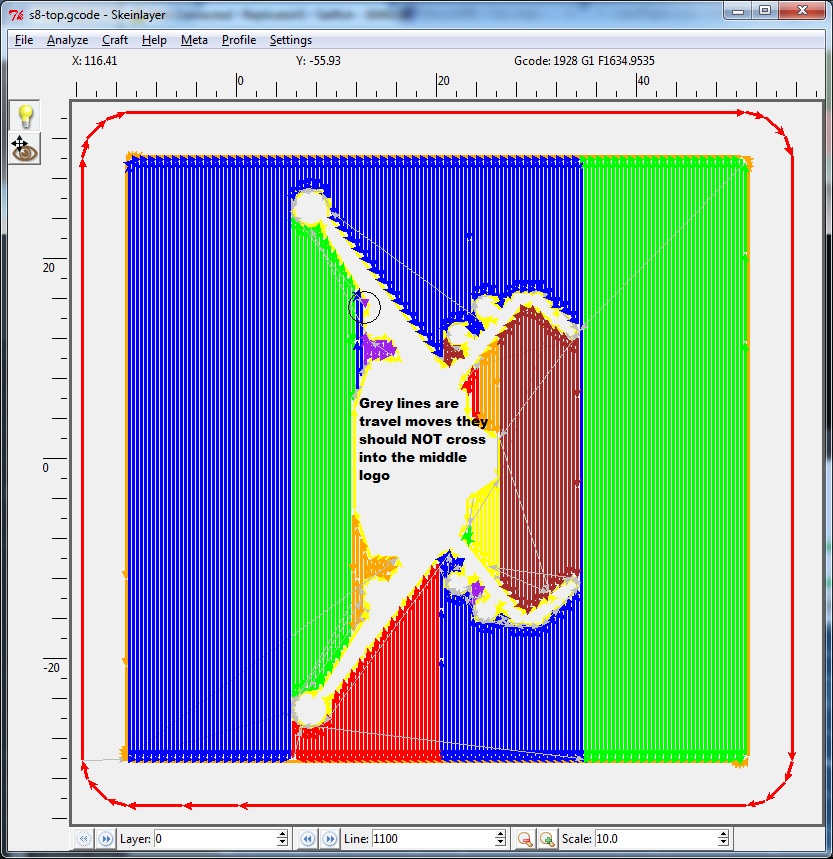
VERY IMPORTANT Pay very close attention to the grey lines. These are travel moves and the MUST NOT cross into the Logo area.
Layer #0. Check All layers with the logo in it
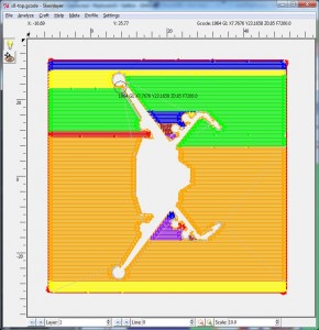
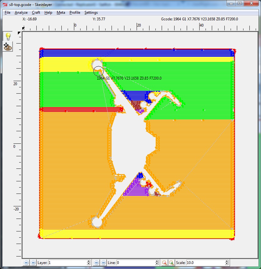
Layer #1. Check All layers with the logo in it
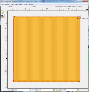
Layer2. The logo is gone since it was only 2 layers .6mm tall
Now that we have the top sliced we can slice the logo with the same settings then print.
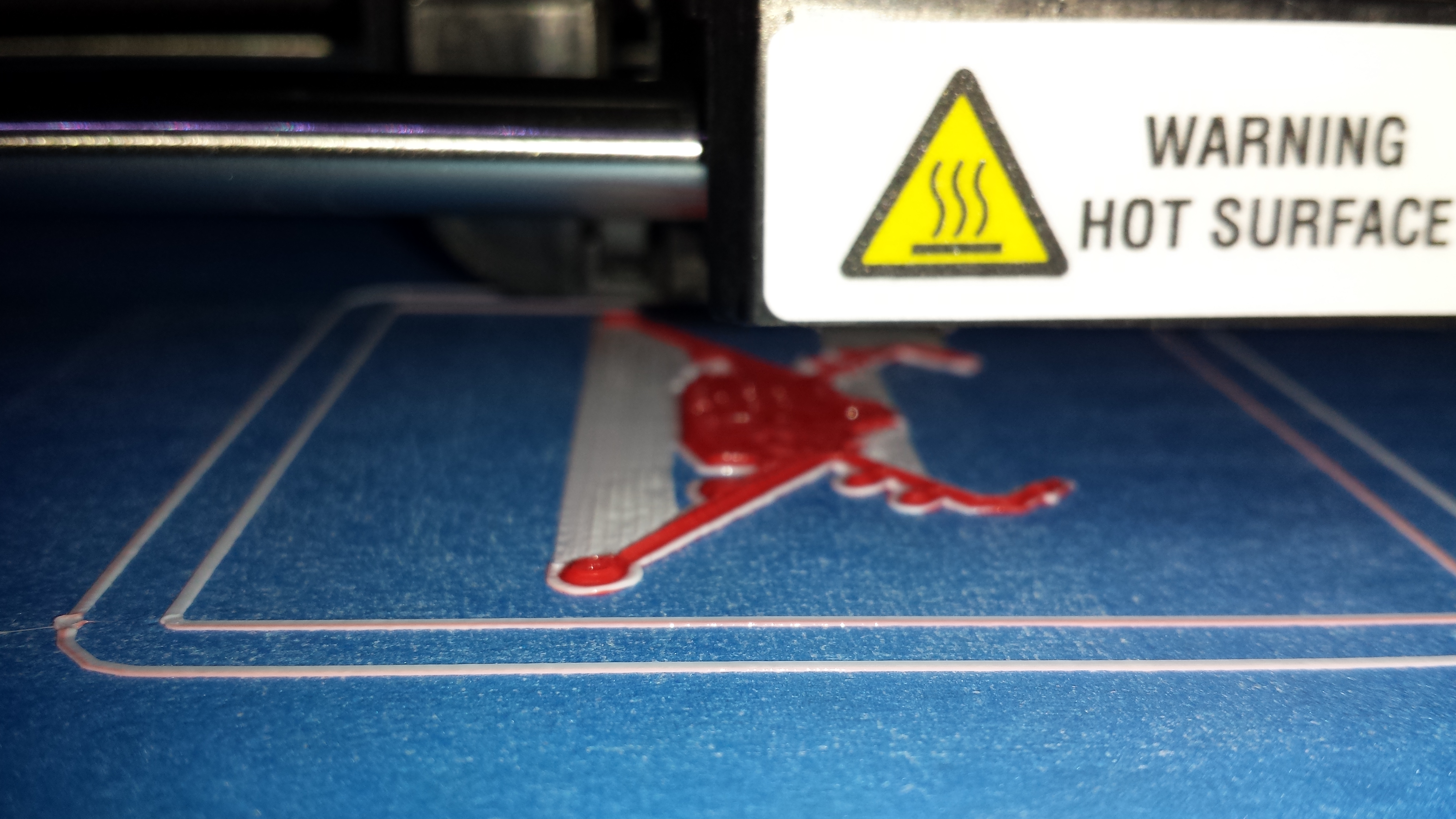
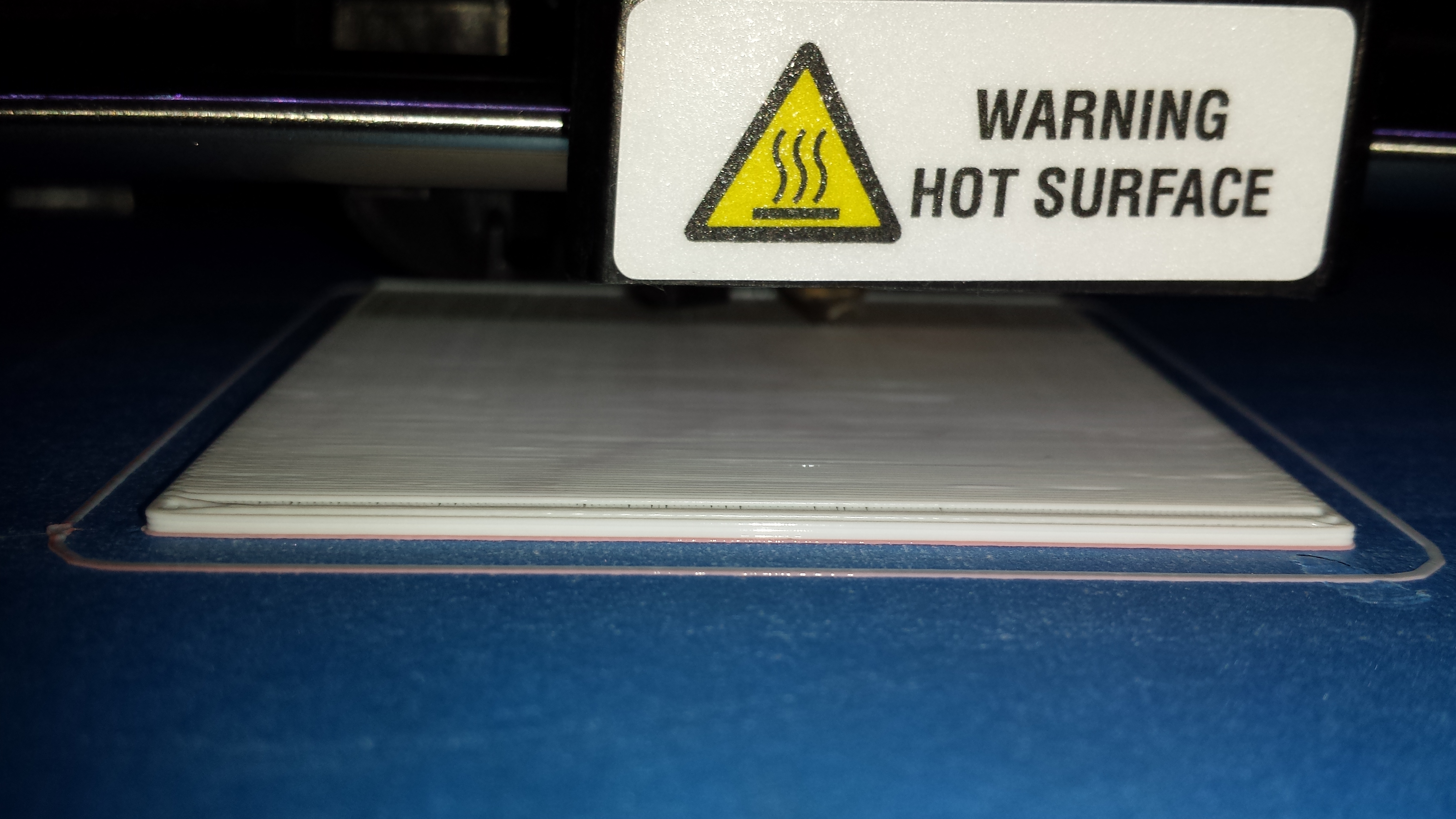
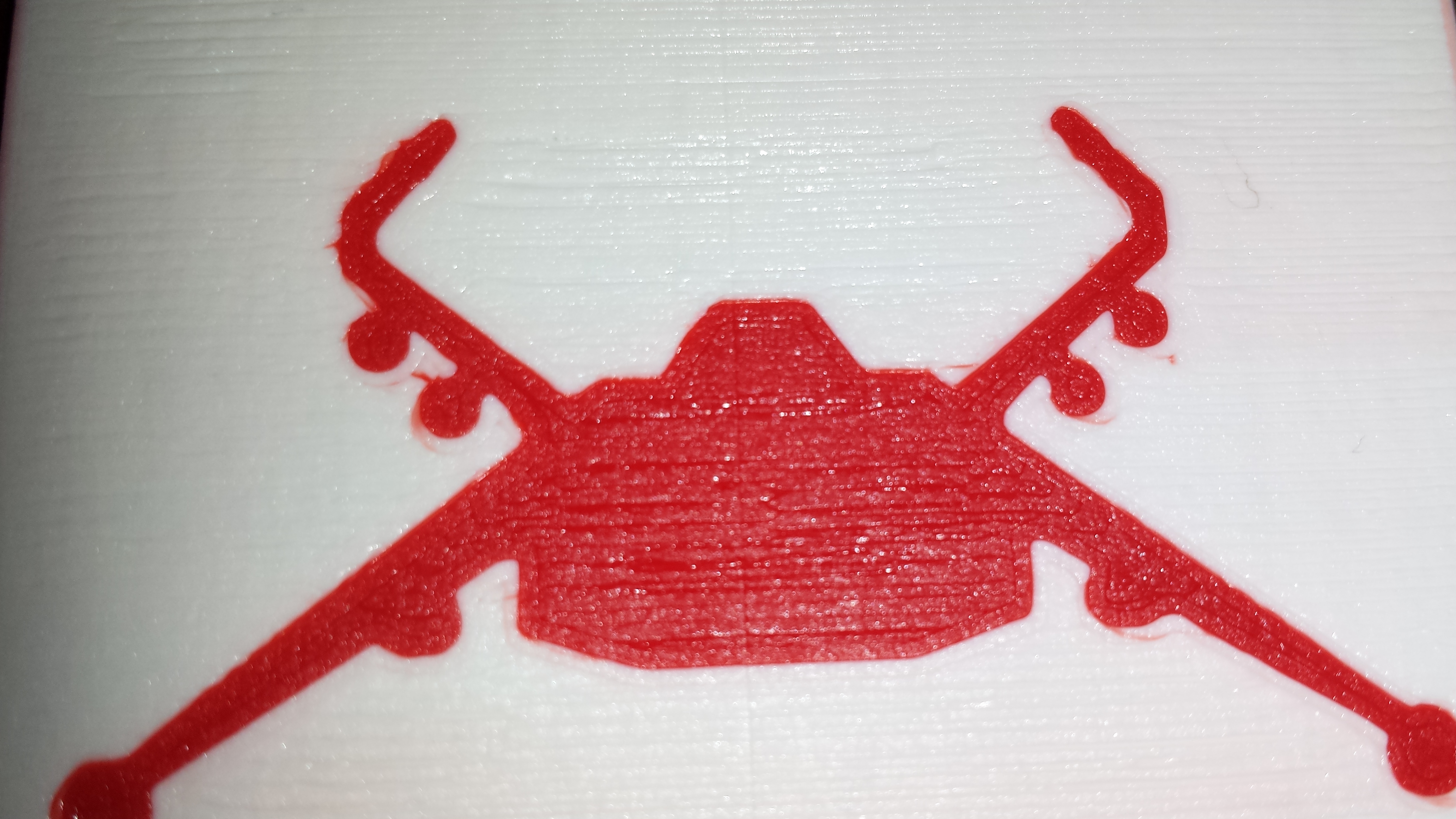
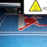
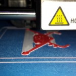
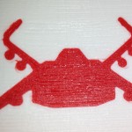
First load the logo color and print the logo as normal. I am using the wipe in my profile so I need to peal that away before the next print.
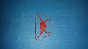
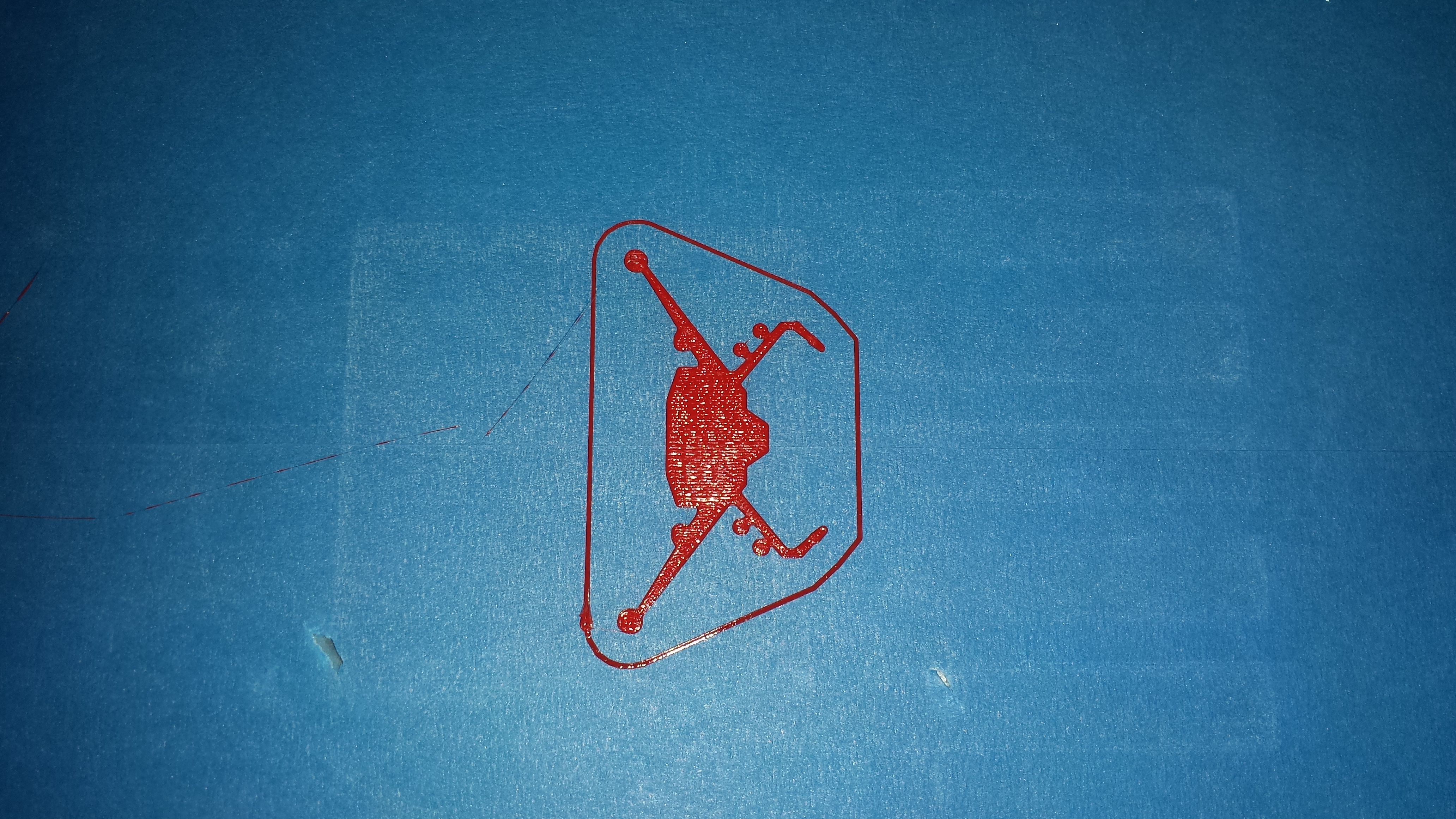
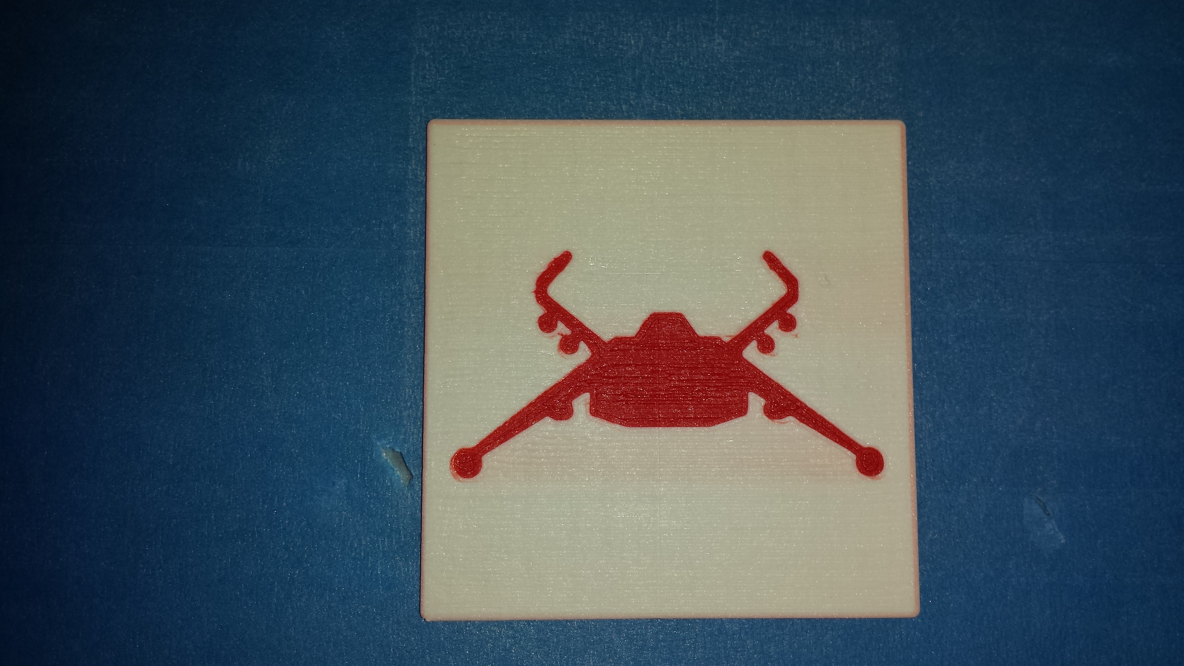
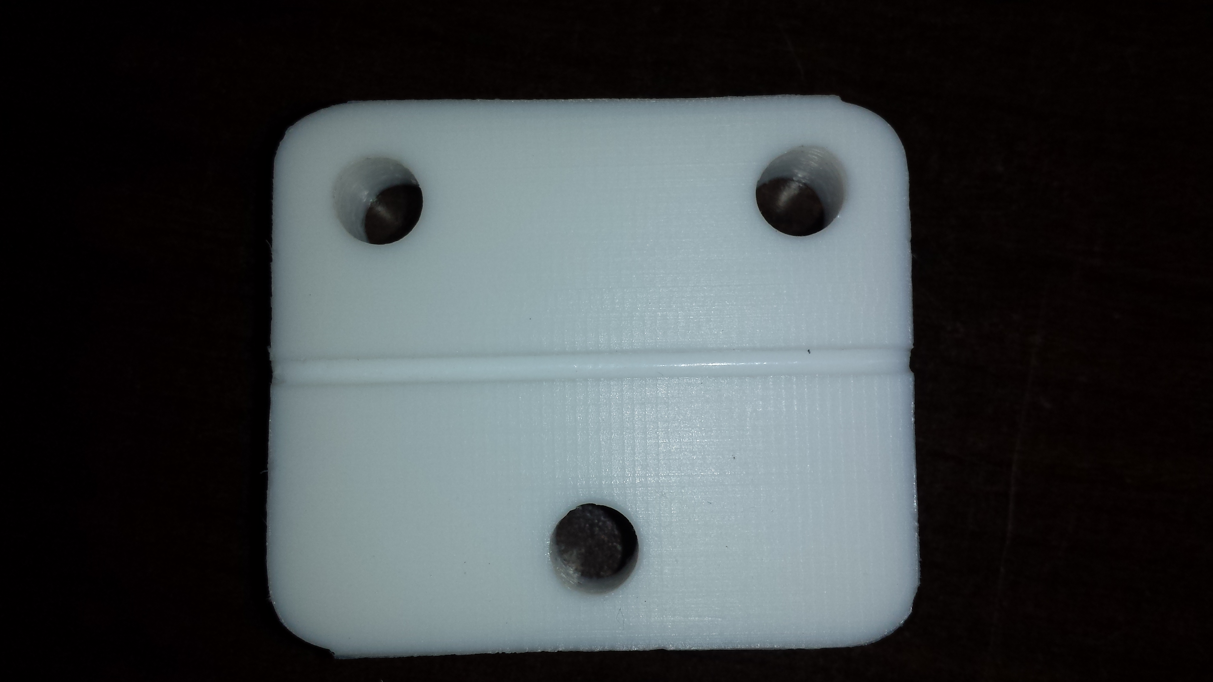
Logo printed
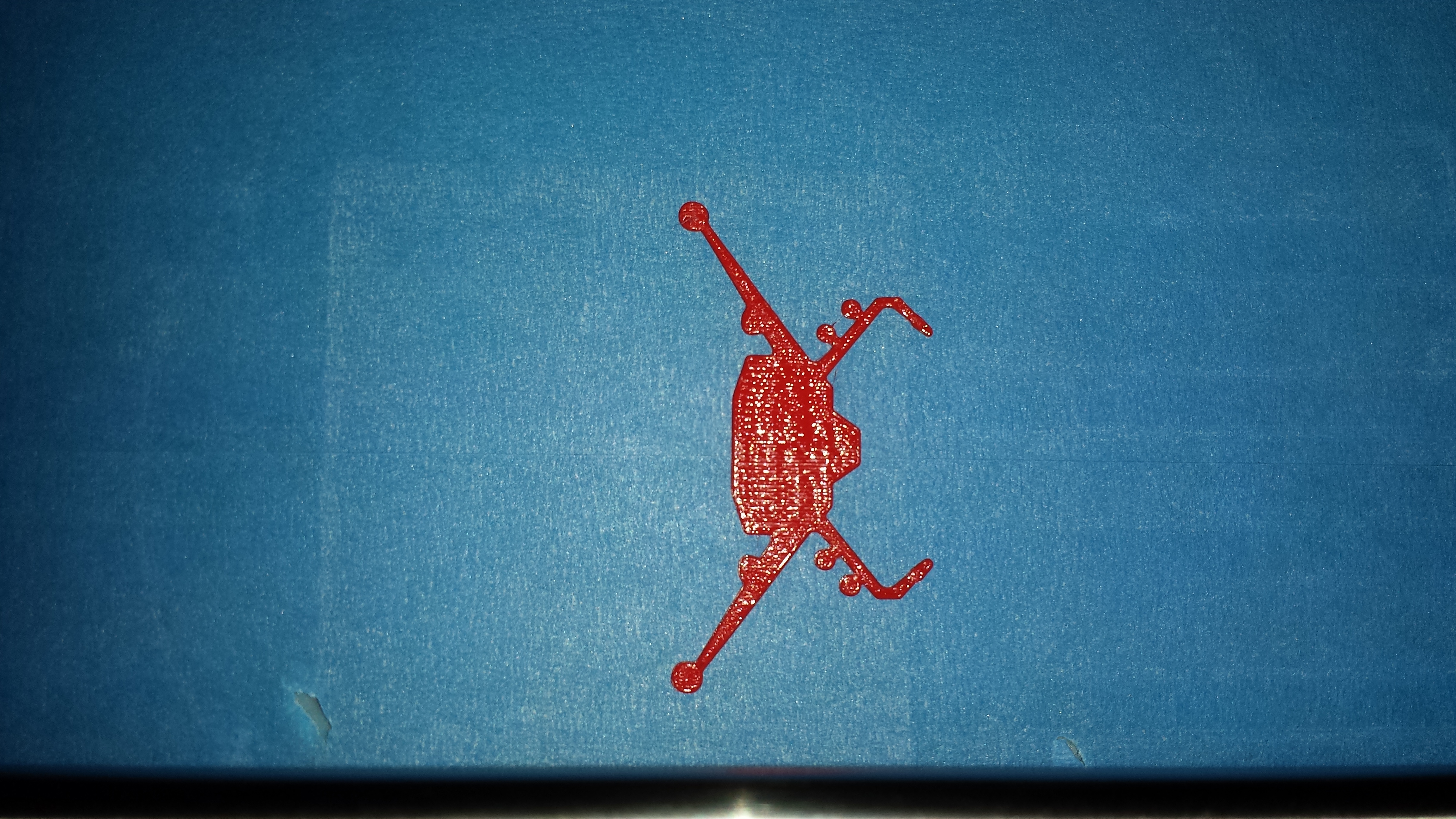
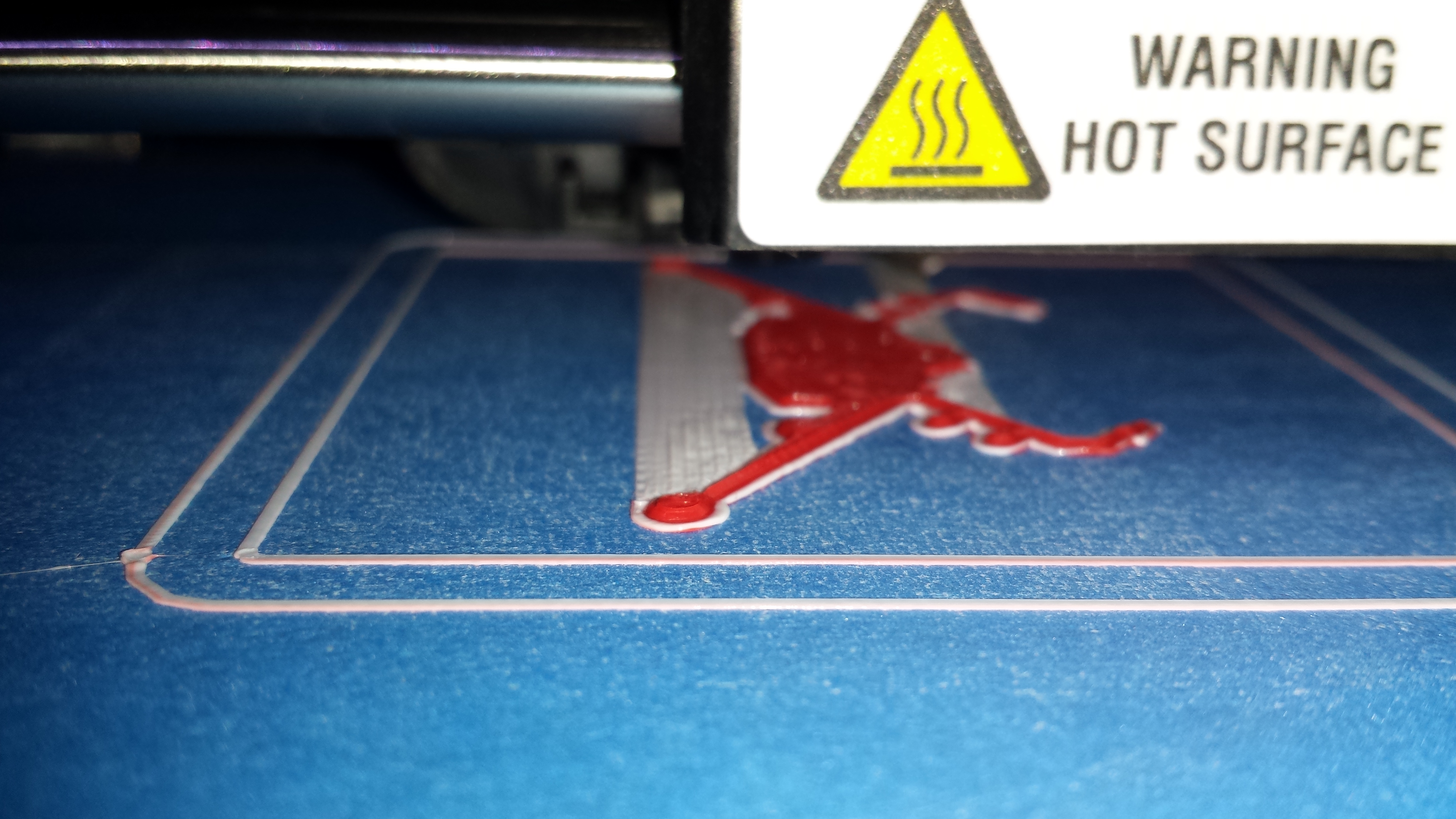
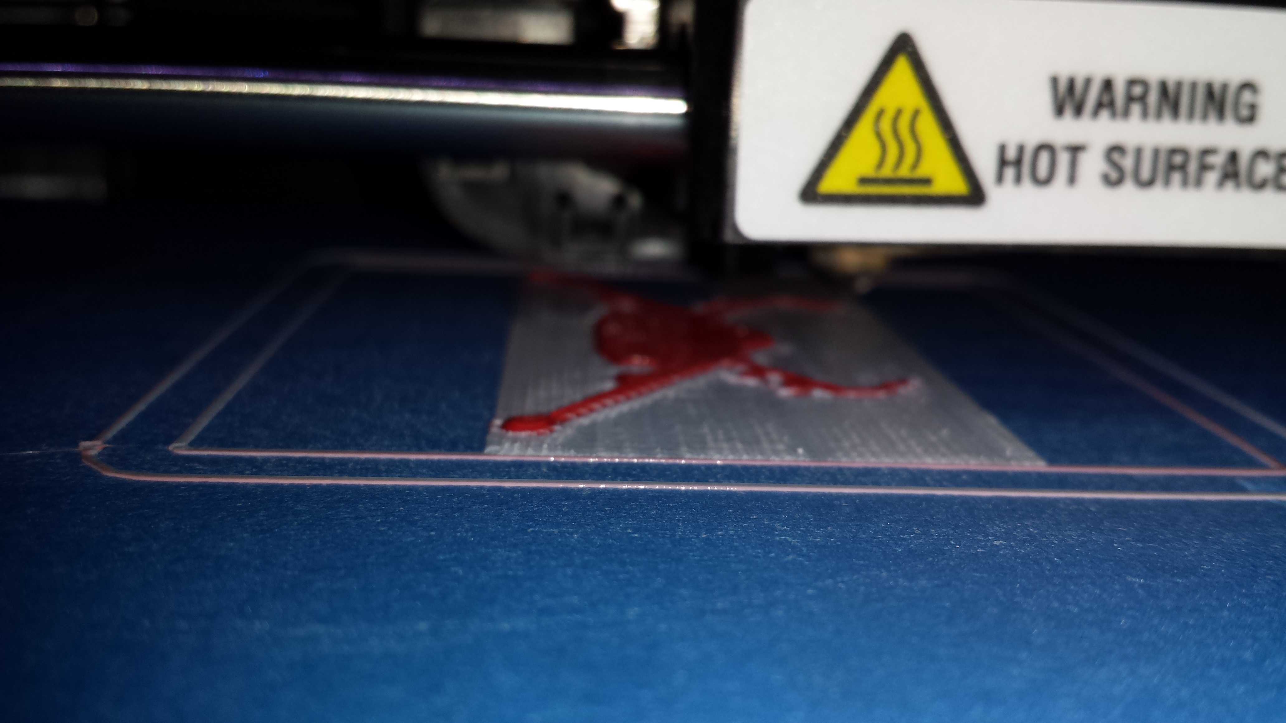
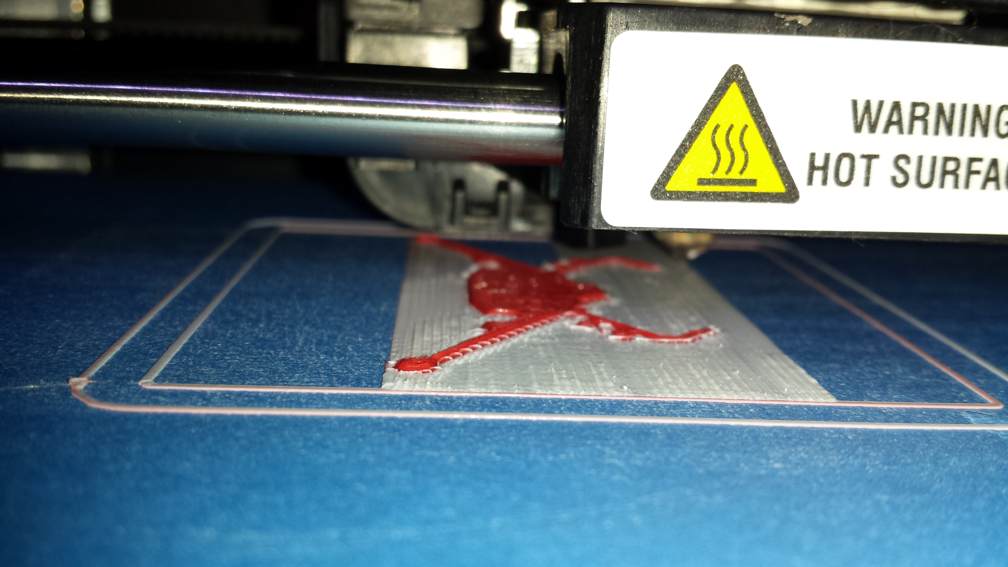
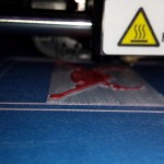
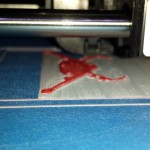
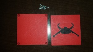
wipe removedNow change filament colors and print the top.

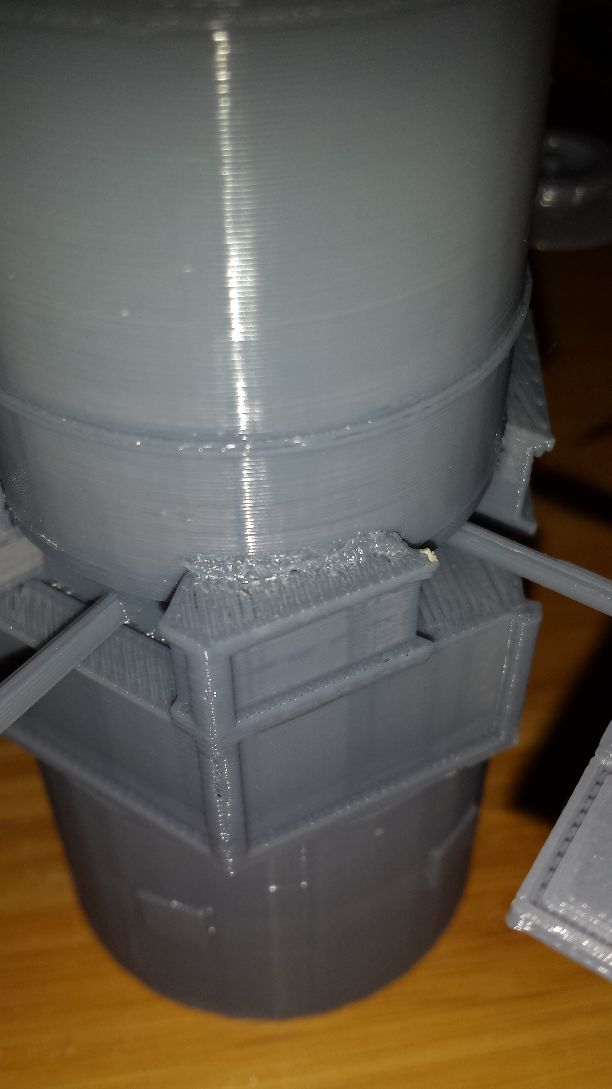
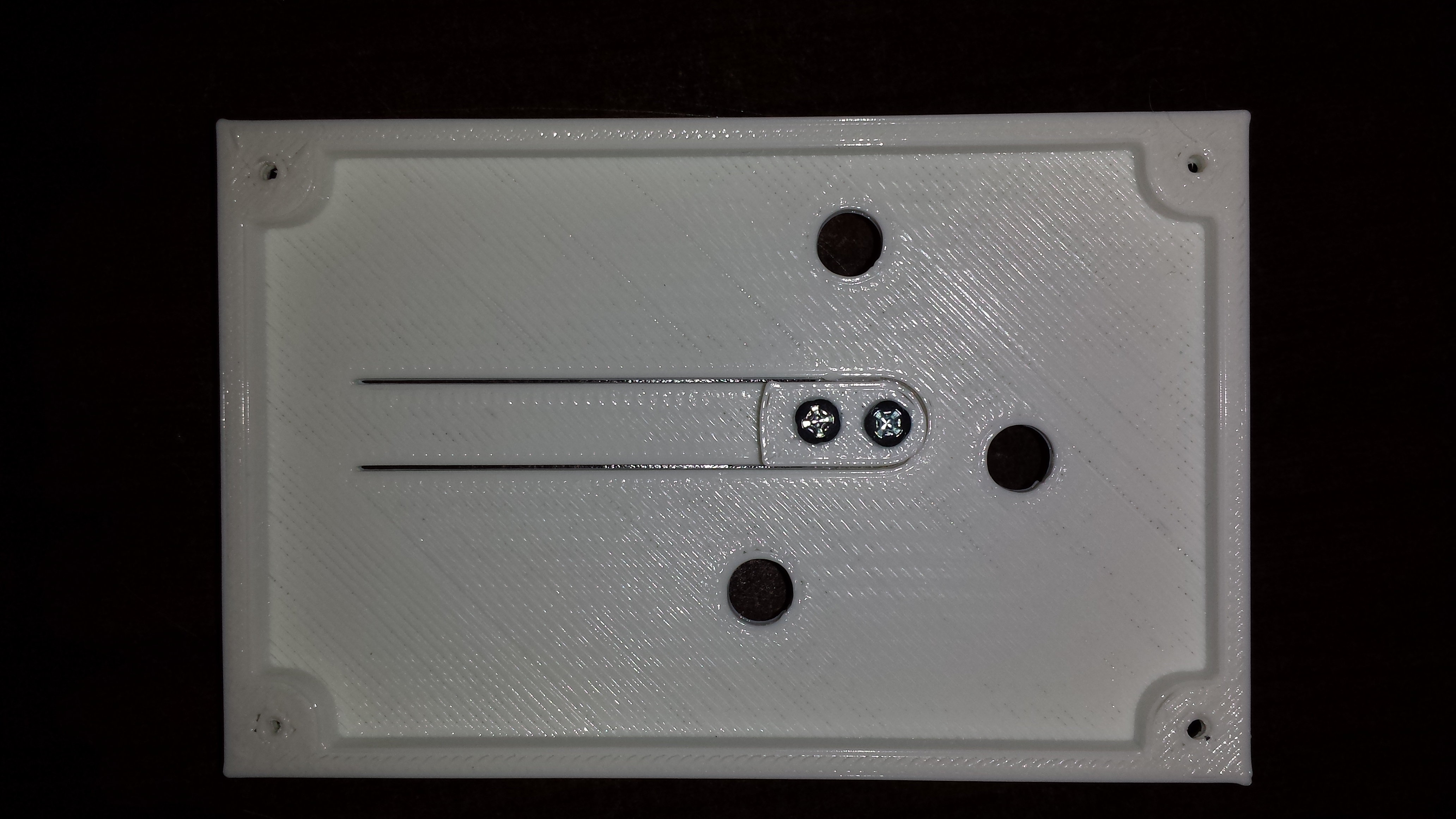
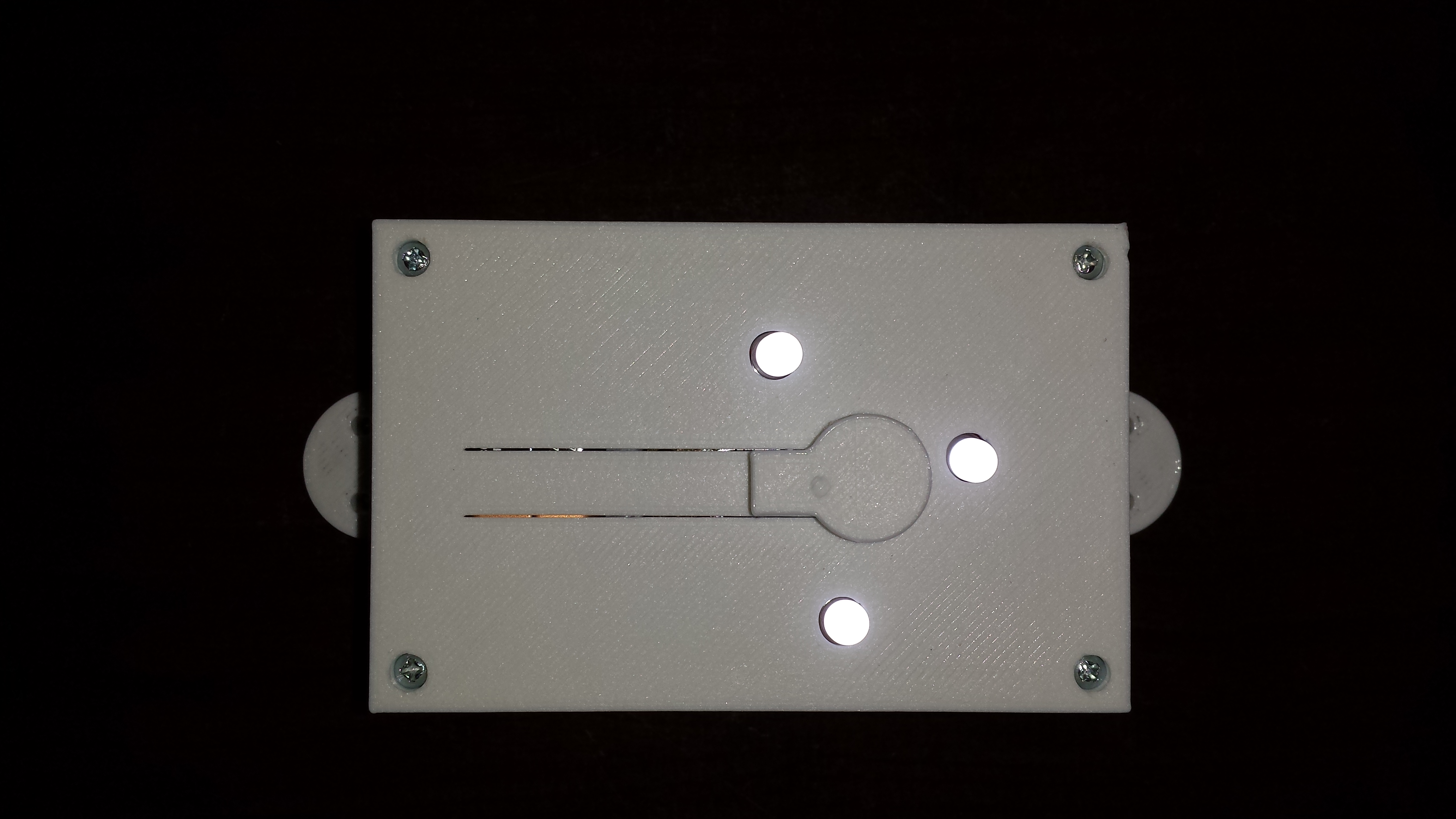
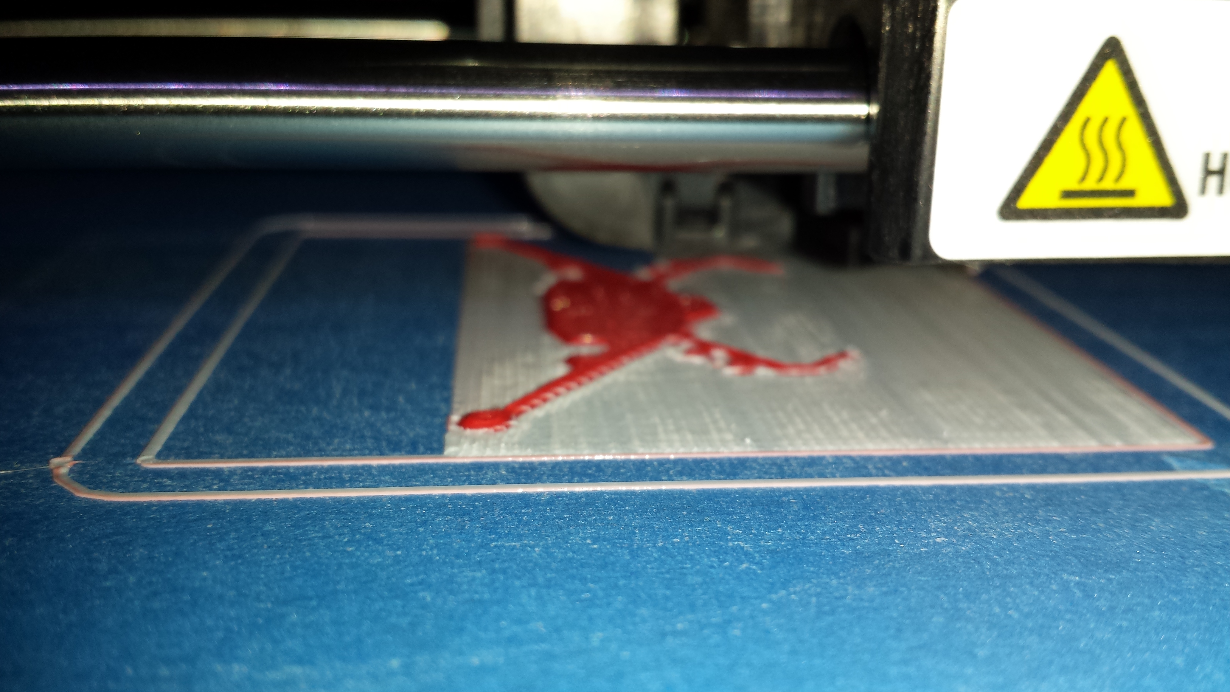
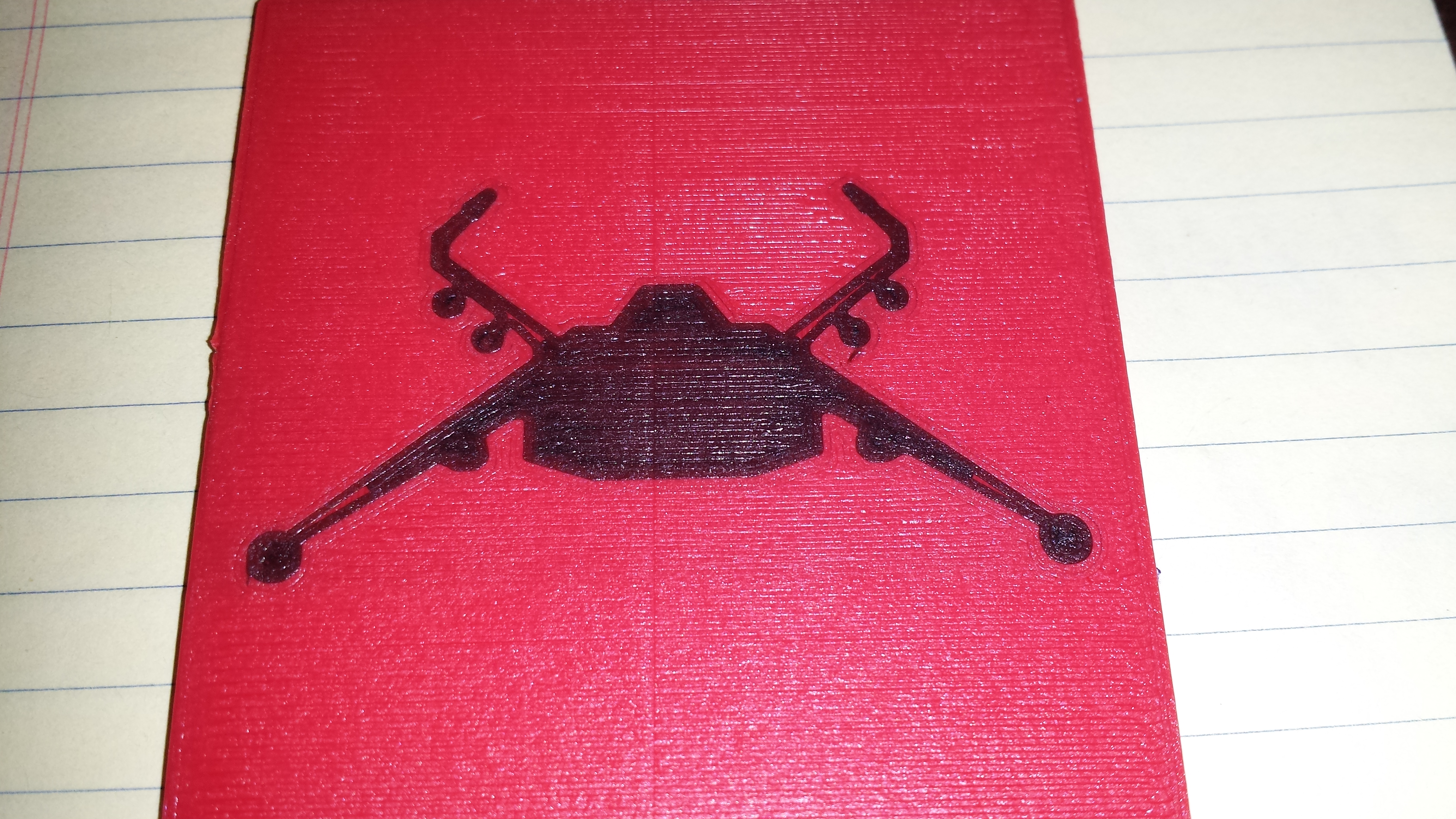
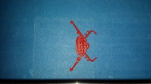
Print complete and it looks great. The bond is amazing. It looks as of it was printed all in one piece.
Here is black on red

Wow that was a long post. Thanks for sticking with me. Hopefully I have proved that you can do two color with a single print head.

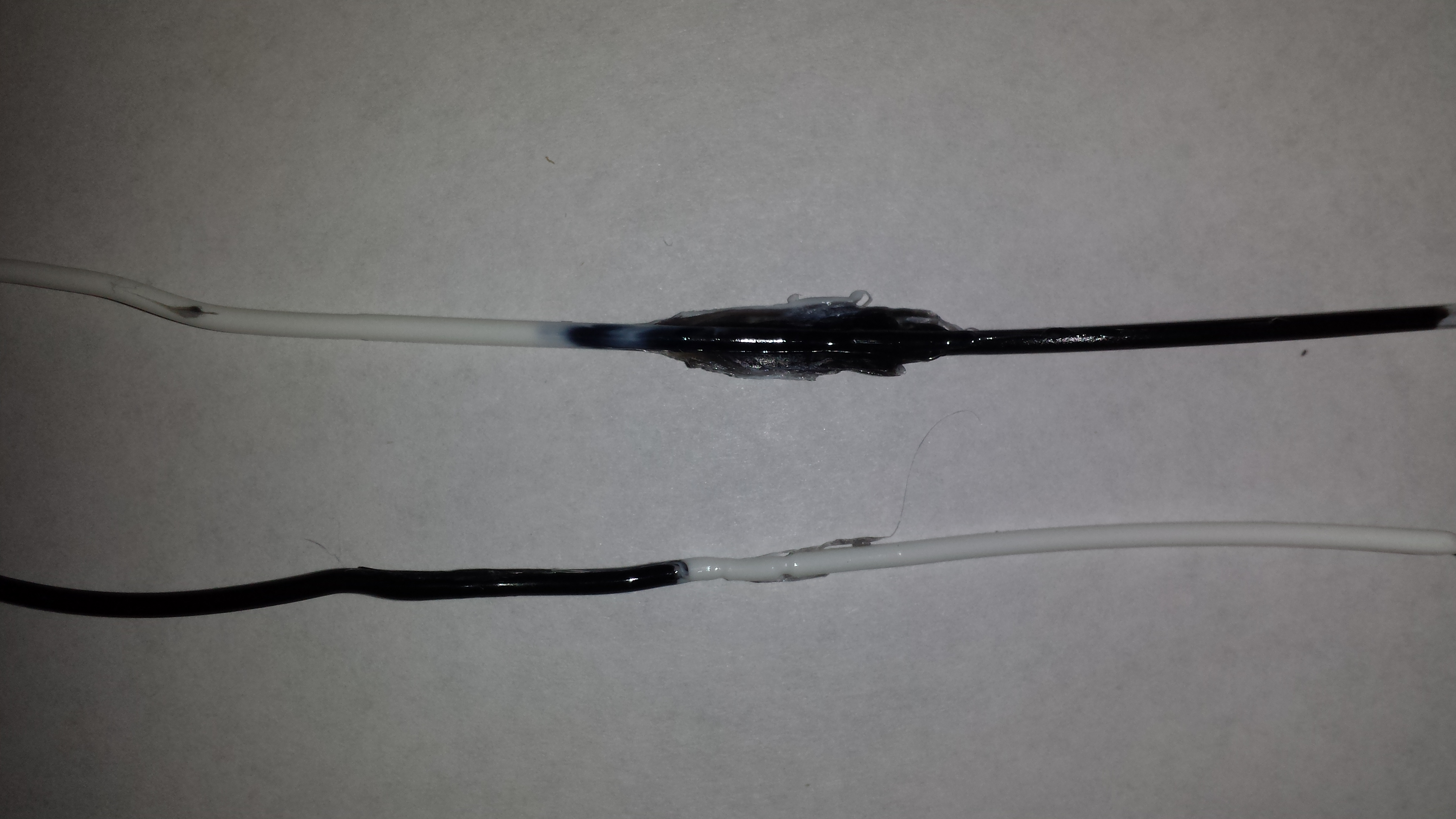
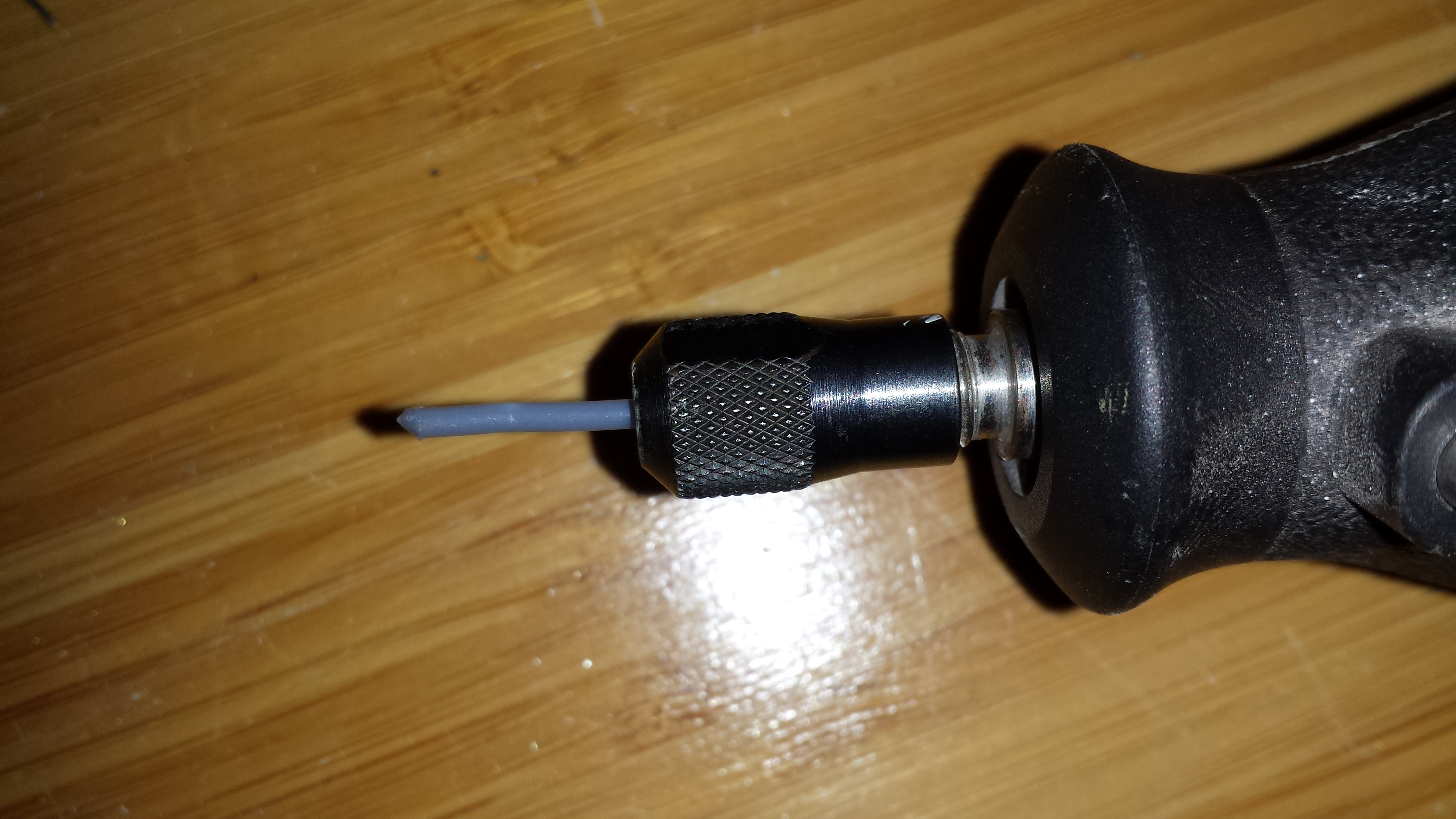 I ran the speed on the Dremel at 3-4 which seemed to work fine for me.
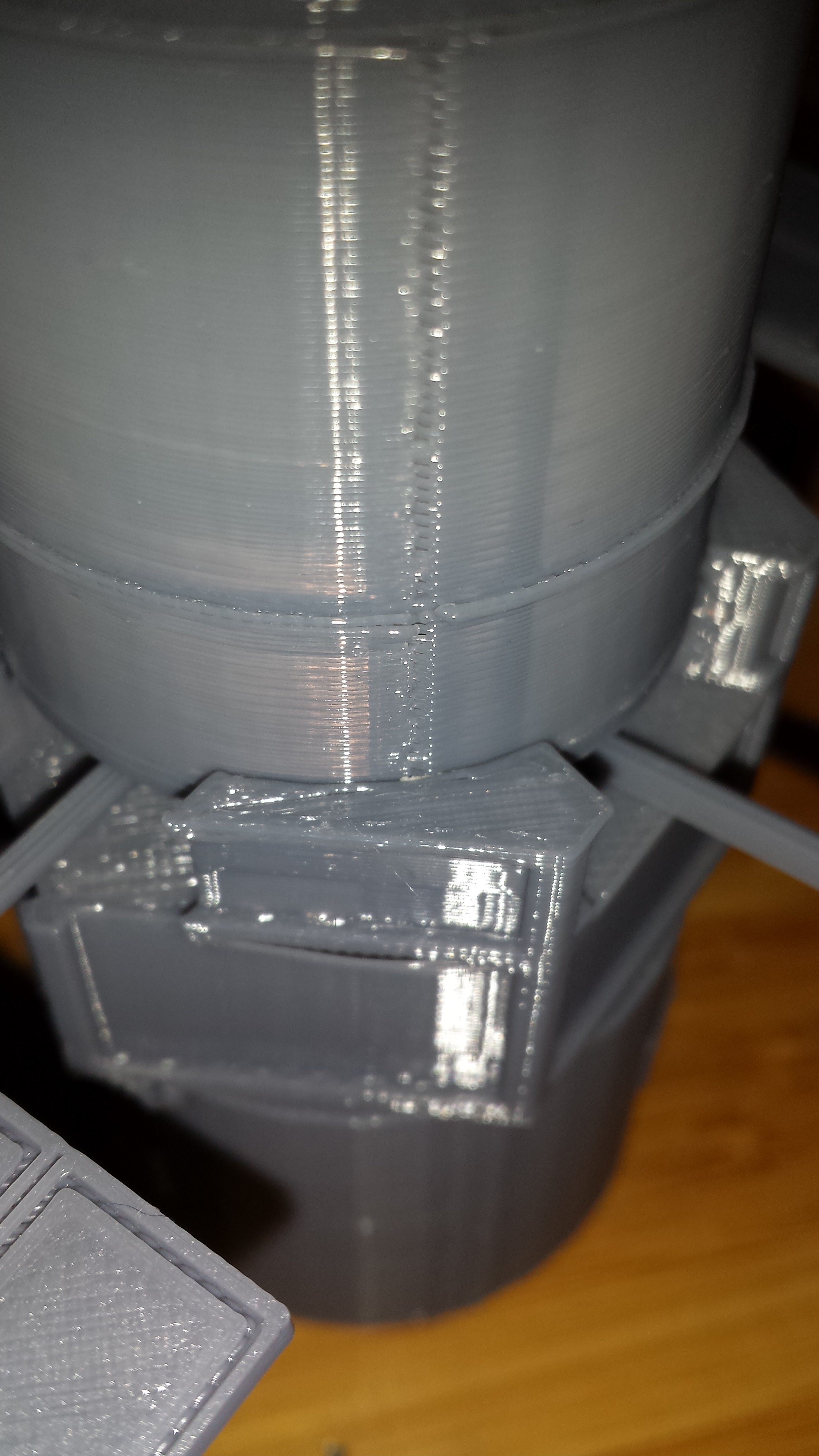 And after:
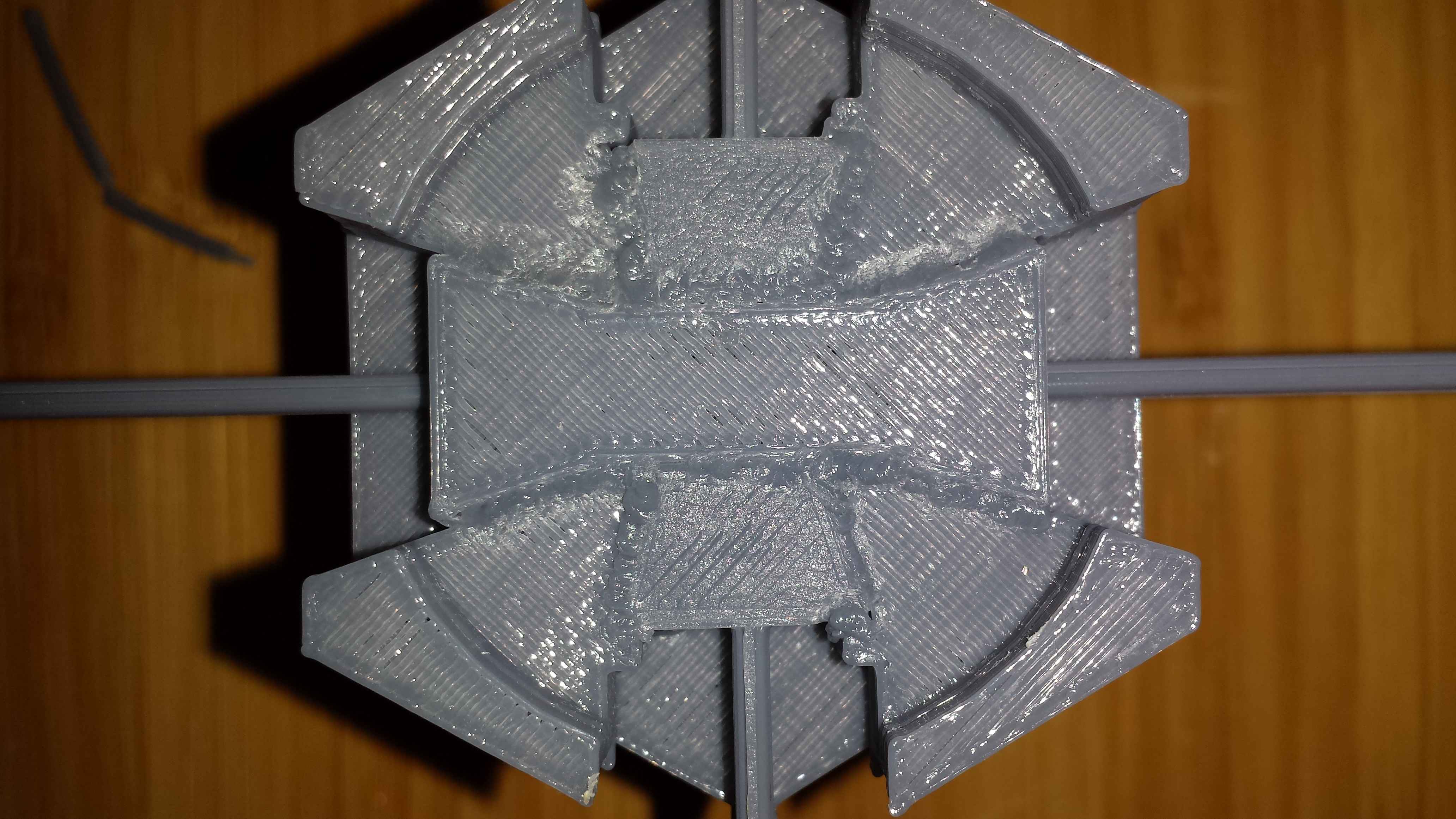
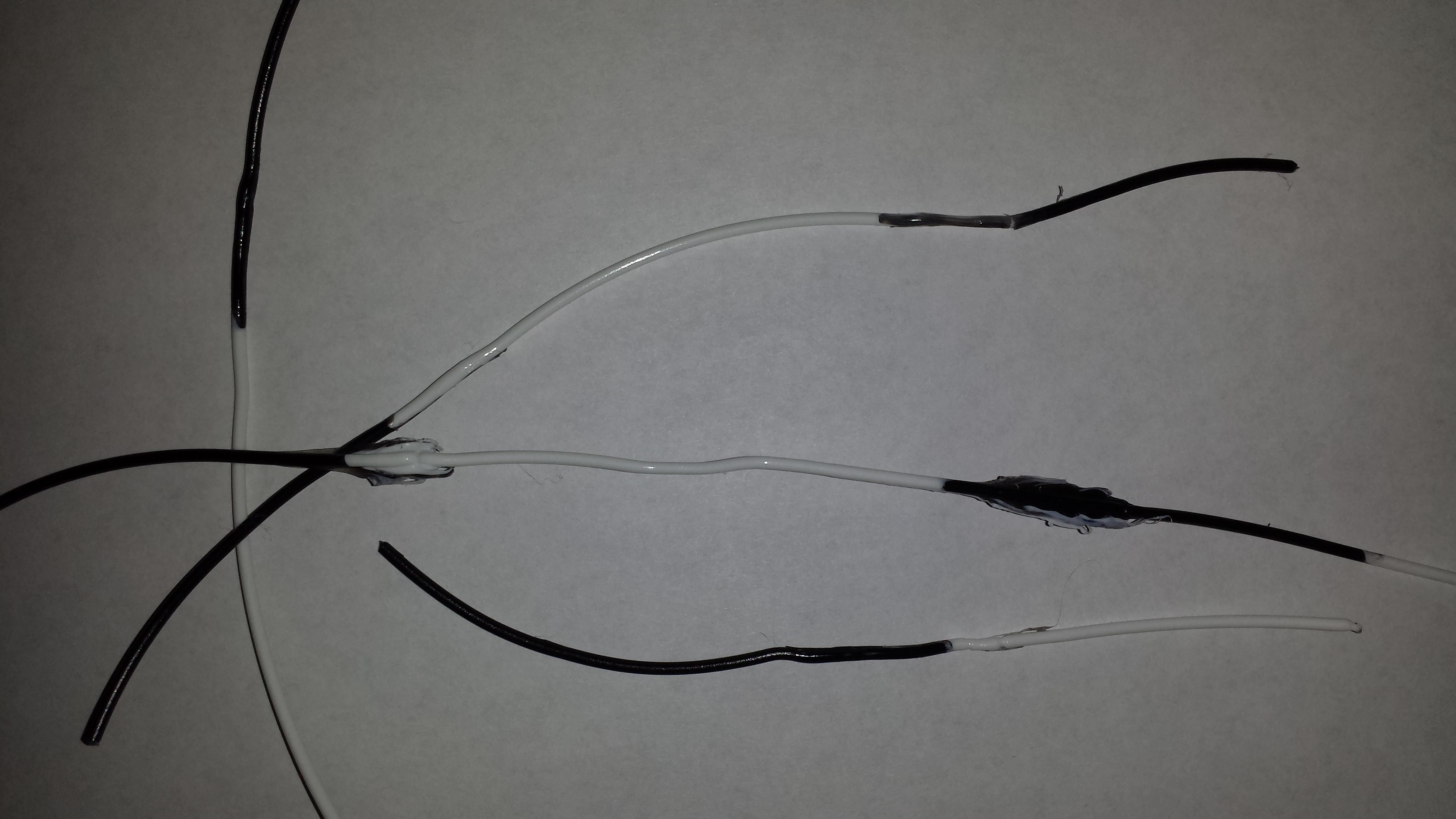
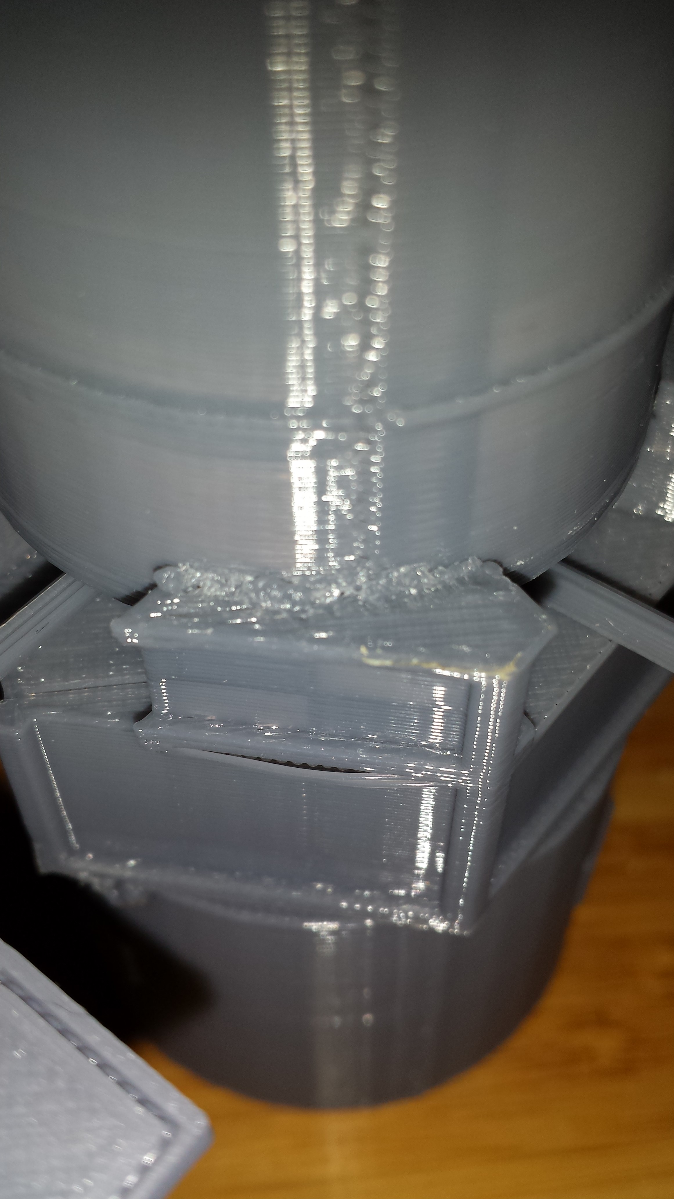 Here are some more joints: